
- Discovery MR750w and SIGNA™ Architect T 3.0T System Service Methods
- 5690002-2EN Revision 4
- 00000018WIA3038C030GYZ
- id_123740611.51
- Oct 11, 2021 3:47:43 PM
Replacing the XRMw gradient coil
Prerequisites
| Personnel requirements | |||
|---|---|---|---|
| Required persons | Preliminary requirements | Procedure | Finalization |
| 3 | - | 8 hours | - |
| Tools and test equipment | |||
|---|---|---|---|
| Item | Quantity | Part number | Manufacturer |
| Extension Cord | 1 | - | - |
| Non-Absorbent Protective Clothing (long sleeve shirt and pants, one per person) | 1 | - | - |
| PPE: Non-Magnetic Safety Shoes, Safety Glasses and Gloves | 1 | - | - |
| Gradient Coil Insertion and Lift Kit | 1 | 2164744-8 | - |
| Shim Tray Extraction Tool (STET) | 1 | 5419765 | - |
| Universal Field Mapping Fixture Kit | 1 | 5266042-4 | - |
| Shim Camera Kit | 1 | 2386028, 2386028-2, or 2386028-3 | - |
| Coolant Removal Kit | 1 | 5269683 | - |
| B0 Power Supply Kit | 1 | 2141701 | - |
| Network Analyzer Service Tool Kit | 1 | 5336593-2 | - |
| Nonmagnetic Titanium Service Tool Kit, Large Set | 1 | 5112581 | - |
| Torque Wrench, 8-50 N m Adjustable, non-magnetic | 1 | 5534134 or 5534134-2 | - |
| 5 Gallon Pail | 1 | 2239133 | - |
| Latex-Free Nitrile Gloves (8 mil) | 1 | 46-194427P400 | - |
| Nonmagnetic 80 N m Fixed Torque Wrench Kit | 1 | 5790177 | - |
| Authorized Personnel Floor Sign(Included in Safety Sign Kit 46-258770G4) | 1 | 2289812 | - |
| Long Room Gray Coil Cart with Cradle (2,444 mm) | 1 of either cart | 2144093 | - |
| Short Room Blue Coil Cart with Cradle (2,416 mm) | 2144093-2 | - | |
| Consumables | |||
|---|---|---|---|
| Item | Quantity | Part number | Manufacturer |
| Isopropyl Alcohol, 70%, USFS-200 | 1 | - | - |
| Scotch Brite Pad | As needed | - | - |
| Cable Tie, 190 Wide X 14 large, nylon | 100 | 46-252283P68 | - |
| Red Loctite 271 (Check expiration date.) | 1 | - | - |
| Never Seize | AR | 46294151P8 | - |
| Loctite #243 (Check expiration date.) | AR | 5415261-2 | - |
| Clean Lint-Free Towels (Kimwipes) | AR | - | - |
| Body Coil Dielectric Tuning FRU Kit | 1 | 5423650 | - |
| Coolant (approximately 15 gallons of coolant required for each XRMB installation) | 4 cartons of four, one gallon containers | 5174313-4 | - |
| Required conditions |
|---|
| Before beginning this procedure, at least one person must complete the training course, GEHC-TECH-AMOL-CT530-01_CURR. |
Read the Hart ID information of the RF Body Coil. Look for the ‘BoardRevision’ information (8 or 16 digits) and record it. (This value is needed to restore body coil dielectric material to the default in Finalization, Step 5.)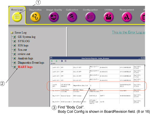 |
| Safety | ||||||||||||||||||||||||
|---|---|---|---|---|---|---|---|---|---|---|---|---|---|---|---|---|---|---|---|---|---|---|---|---|
|
Before working in any GE Healthcare MR suite or performing any GE Healthcare service procedure, you must:
If you have any safety concerns at any time, do not begin work or immediately stop work and move to a safe location. Immediately contact your supervisor or site safety officer for instructions on how to proceed. | ||||||||||||||||||||||||
| ||||||||||||||||||||||||
About this task
Overview
This procedure describes the replacement of the XRMw gradient coil using the Gradient Coil Insertion and Lift Kit (2164744-8), and requires disposal of coolant. Tell the customer about coolant disposal, and then follow the proper customer coolant disposal procedure.
Preliminary tasks
Procedure
- Identify the gradient and busbars to order. See Figure 2.
Figure 2. Gradient replacement ordering guide 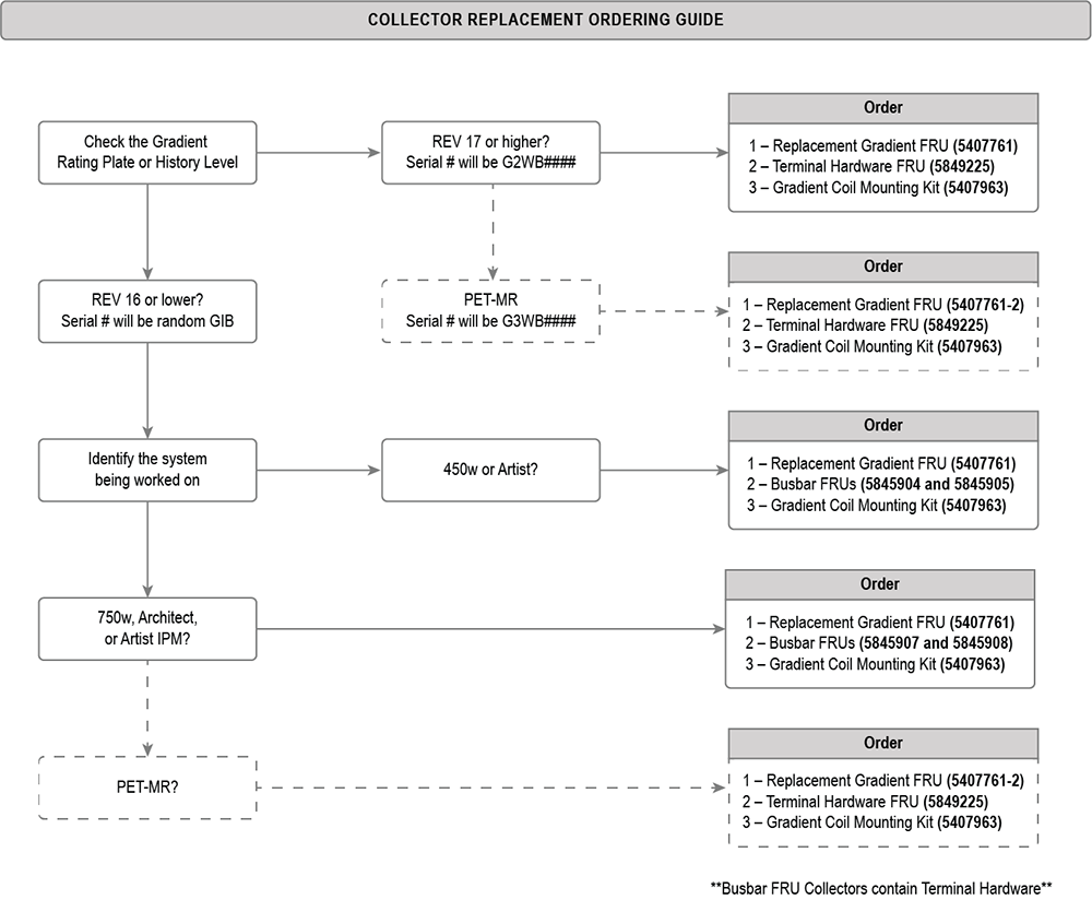
If the magnet is ramped, remove all passive shim trays from the XRMw gradient coil before the installation and store them in a safe place. (The procedure for replacing shim trays can be found in the Magnet and Cryogen Manual for Passively Shimmed Magnets (5495018.)Notice 
Removing coolant
Procedure
LOTO should already be applied to the HEC. [Refer to the MR Service Safety Manual (5452735)].DANGER 
The connection between hose and fitting is pressure only. To properly remove a hose from the fitting, carefully cut a slit (1) on the manifold hose (avoid damaging the water fitting), and slide it off the barb to disconnect the supply manifold from the fitting.CAUTION - Repeat for the return line.
- Retain the fittings at the site.
Figure 3. Barb fitting and valve 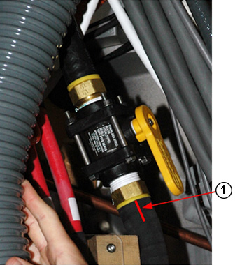
Slowly disconnect the supply, then the return manifold from the valve, and drain the fluid into the bucket.Notice Figure 4. Draining manifold coolant 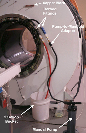
Cable removal and busbar cable disconnection
Procedure
- At the service end, remove the safety covers from the end of the Y and XZ busbar cable connections.
Figure 5. Y and XZ busbar cables (service end) 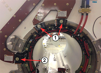
1 XZ safety covers 2 Y safety cover Note: Do not remove the clamps on the busbar leads. - Remove and discard the six flanged M10 nuts and Nord-Lock washers securing the busbar lugs to the gradient coil, and slide the busbar terminal lugs off the coil studs.Note:
Never use the nonmagnetic torque wrench to loosen connections, the torque wrench has a range of 10 - 50 N*m ( 8 – 35lbf*ft), removing Nord-Lock© or Spiralock© threads may exceed the limit of this wrench and destroy the ratchet components.
- (For gradient REV 16 or lower (see History label on gradient)) Terminals will be an M10 connection.
- (For gradient REV 17 or higher (Unit Build # and Serial # will be G2BW####, or G3WB#### for PET/MR)) Terminals will have an M12 connection. An "M12" indicator will also be on the busbars. Remove and discard the six M12 SmartBolts and Nord-Lock washers securing the busbar lugs to the gradient coil.
Figure 6. Y and XZ busbar cable connections 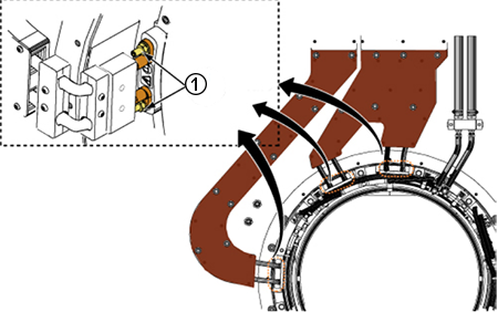
1 Nuts on cable terminal studs (M10) Figure 7. SmartBolts on M12 cable terminal lugs 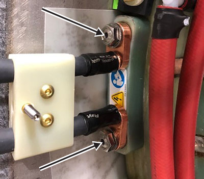
- Remove the following cables from the gradient coil:
- Temperature sensor cable at the rear of the magnet
- Ground wire
Figure 8. Ground wire 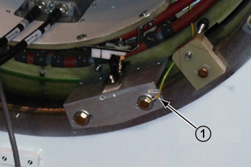
1 Ground wire
Preparing for XRMw coil removal
Procedure
Use a pen and mark along the edge of the front body coil mounting brackets (1) and remove them (2).Notice Figure 9. Front mounting brackets 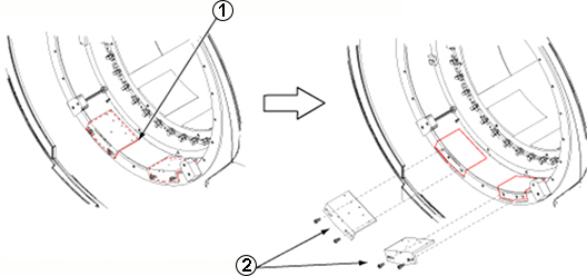
- Attach three adapter plates (5338222) to the patient end of the gradient coil at 3, 9, and 12 o'clock positions with M10 x 20 mm bolts and M10 nuts.
Figure 10. Adapter plate on gradient coil (patient end) 
Figure 11. Bolt with nut 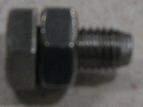
- Attach two adapter plates (5338223) to the service end of the gradient coil at the 3 and 9 o'clock positions with M10 x 20 mm bolts and M10 nuts.
Figure 12. Adapter plates on gradient coil (service end) 
- Retrieve the mounting plates [5161985 (1) and 5161983 (2)] and the two tube guide roller assemblies [5308402 (3)] from the gradient coil insertion and lift kit shipping crate, and securely attach the roller assemblies to the mounting plates.
Figure 13. Roller assemblies and mounting plates 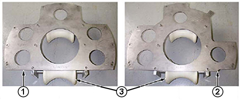
1 Mounting plate, patient end 2 Mounting plate, service end 3 Roller assemblies
Align the mounting holes on the patient end of the mounting plate (5161985) with those in the adapter plate (5338222), which includes the guide roller assemblies already attached to the gradient coil, and secure them using the M10 x 20 mm bolts and M10 nuts.Notice Figure 14. Mounting plate with roller assemblies (patient end) 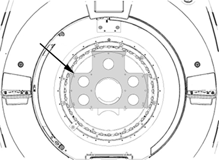
- Align the mounting holes on the service end mounting plate (5161983) with those in each adapter plate (5338223 and 5338224), already attached to the gradient coil, and secure them using M10 x 20 mm bolts and M10 nuts.
Figure 15. Mounting plate with roller assemblies (service end) 
- Remove the brass M10 x 30 mm bolt and M10 nut from each of the two rear axial stops.
Figure 16. Removing rear axial stop 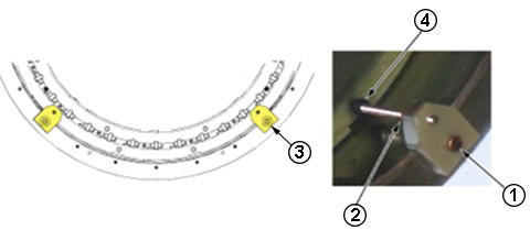
1 M10 x 30 mm bolt, brass 2 M10 nut, brass 3 Rear axial stop 4 Stud on axial stop - Attach the wing adapters (5339882) (2) to the tube support plate with stainless steel 0.75 inch 16 x 1.25 inch long bolts.
Figure 17. Support plate with wing adapters 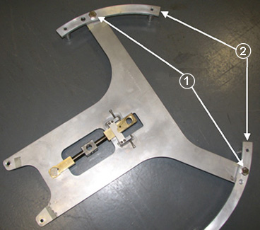
- Before installing the tube support plate:
- Detach the rear service end wedges at the locations 1 and 2 by removing the brass bolt (1) and washer (2) from each.
- Remove the Y gradient cables.
Figure 18. Wedges at locations 1 and 2 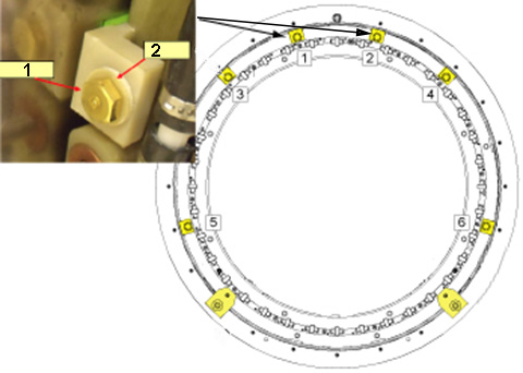
- Attach the tube support plate (1) to the magnet service end by inserting the 100 mm M10 x 25 stainless steel studs (5303994) 3/8 inch (13 mm) into the magnet, and secure them with the stainless steel washers and M10 nuts from the gradient coil insertion and lift kit.Note: Make sure the six extension spacers face toward the magnet interface ring and the nuts are securely tightened.
Figure 19. Support plate attached on interface ring 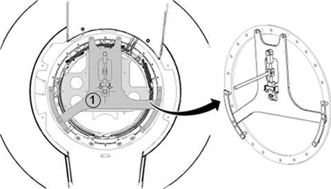
Removing the XRMw coil with a cart
Procedure
Warning 
Put the tube jacking assembly (5191132) in the cart, making sure the back of the jack assembly fits properly into the cart.Notice Figure 20. Jack assembly placement 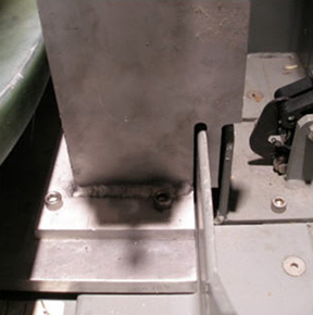
- Maneuver the cart to the patient end of the magnet, and position it in front of the magnet with at least a 2 inch (50.8 mm) gap between the cart and the magnet interface ring (required for lower wedge removal).
Figure 21. Gap between magnet and cart 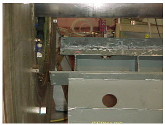
- Retrieve the male insertion tube (2284929) and tube standoff (5191626).
- Attach the tube standoff to the male insertion tube using the 4 inch, 0.375–16 UNC hex socket screw (5303993) included in the gradient coil insertion and lift kit.
- After the standoff is secured to the tube, attach the tube pilot shaft to the standoff.
Figure 22. Attaching the standoff to the insertion tube 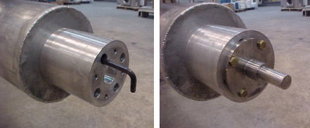
- Remove the PVC shield from the brass thread of the male insertion tube.
Figure 23. PVC shield for the brass thread 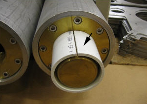
- Slide the male insertion tube through the tube guide roller assemblies at both sides of the gradient coil, push the pilot shaft through the support plate mounting bearing, and insert a nonmagnetic safety pin through the hole in the pilot shaft.
Figure 24. Tube pilot shaft and support plate 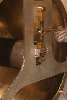
With one person holding the male insertion tube to keep it from rolling, two people should get the female insertion tube from the shipping crate and thread the two tubes together.Notice Note: Each of the two pieces of the gradient insertion tool weighs less than 35 lb (15.9 kg).Figure 25. Setting up the insertion tube assembly 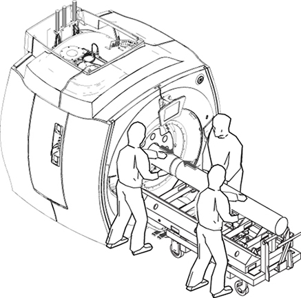
Recheck the centering of the cart left-to-right with respect to the magnet bore, and adjust the longitudinal alignment of the cart if necessary.Notice - Simultaneously raise the tube jack and the support plate mounting bearing to lift the gradient coil.
Figure 26. Raising the XRMw gradient coil 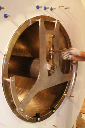
Properly secure the gradient coil to the coil cart with gradient coil shipping bracket (5357473).CAUTION 
Remove the insertion tool from the gradient coil.CAUTION
Preparation before XRMw installation
Procedure
- Remove the shipping brackets securing the gradient coil to the cart.
Figure 27. XRMw shipping bracket(s) 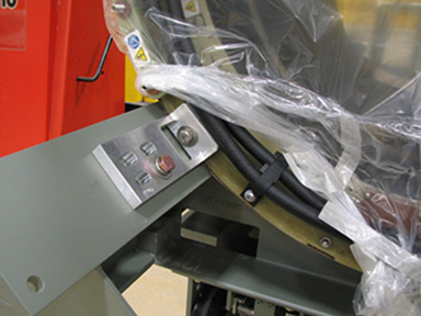
- Remove the gradient coil cradle fasteners (two per side) from the cradle.
Figure 28. Removing cradle fasteners 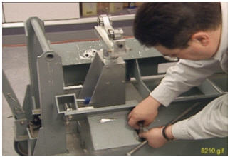
Align the mounting holes on the patient end of the mounting plate (5161985) with those in the adapter plate (5338222), including the guide roller assemblies already attached to the gradient coil, and secure them using the M10 x 20 mm bolts and M10 nuts.Notice Figure 29. Mounting plate with roller assemblies (patient end) 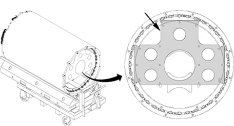
- Align the mounting holes on the service end of the mounting plate (5161983) with those in each adapter plate (5338223 and 5338224), already attached to the gradient coil, and secure them using M10 x 20 mm bolts and M10 nuts.
Figure 30. Mounting plate with roller assemblies (service end) 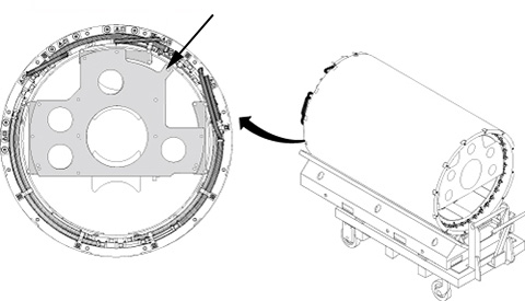
Installing the XRMw gradient coil
Procedure
- Retrieve the tube support plate assembly (2284928-2) from the gradient coil insertion and lift kit shipping crate, and make sure the Y gradient cables are removed from the magnet.
- Make sure the two wing adapters (5339882) are attached with 0.75 inch, 16 x 1.25 inch long stainless steel bolts (1).
- Secure the tube support plate assembly and wing adapters to the magnet flange at the service end with M10 studs, spacers, and M10 nuts (2).
Figure 31. Attaching tube support plate 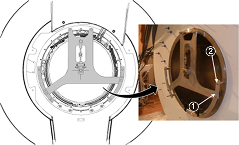
- Adjust the horizontal adjustment screws (3) on the tube support plate assembly until the tube support bearing (4) is centered left-to-right.
Figure 32. Adjusting support plate 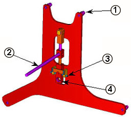
1 Spacer 2 Vertical adjustment lever 3 Horizontal adjustment screws 4 Support bearing
Place the tube jacking assembly (5191132) in the cart, making sure the back of the jack assembly fits properly into the cart. (See Figure 20.)Warning - Raise or lower the cradle of the cart as required to vertically align the tube support plate at the magnet and the gradient mounting plates at the gradient coil.
Figure 33. Adjusting cart height 
With one person holding the male insertion tube to keep it from rolling, two people should obtain the female insertion tube from the shipping crate and thread the two tubes together.Notice Figure 34. Setting up insertion tube assembly 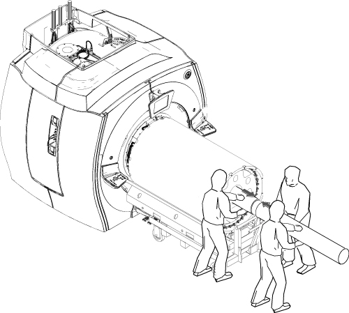
Push the complete insertion tube assembly into the magnet bore so the tube pilot shaft is close, but not touching, the tube support plate.Notice Figure 35. Complete insertion tube assembly 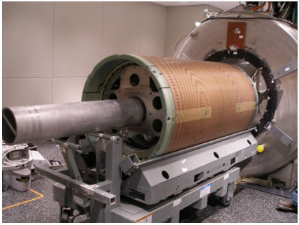
- Mount the alignment tools as follows:
- Gradient alignment T-block (5389303) (1) to the patient end of the gradient coil (2), using two M10 x 25 stainless steel flat-head socket cap screws (5389090-3) (3) at ±15 degree hole in the coil flange.
- Radial alignment tool (5266408) (4) to the patient end of the magnet, using two M10 x 25 stainless steel Bolts (46-318508P20) at ±15 degree hole in the magnet interface ring.
Figure 36. Alignment tools 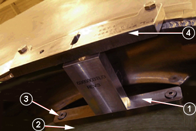
- Carefully rotate the gradient coil and stop it when the T-block (5389303) starts to make contact (1) with the alignment tool (5266408).
Figure 37. Aligning the gradient coil (front-to-back) 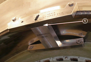
- Align the gradient coil clocking direction as follows:
- Rotate the coil into position until the center hole of the alignment T-block (5389303) aligns with the slot of the alignment tool (5266408) on the magnet.
- Insert the thumbscrew (1), part of the radial alignment tool, through the slot and thread it into the alignment T-block on the coil, engaging the rotational locks on the carriage assembly to hold the position.
Figure 38. Aligning the gradient coil (clocking) 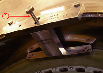
- Place one each gradient mounting pad (5352696) on the bottom of the bore at the patient end and service end of the magnet so its outer edge is 5 mm, ±1 mm inward from the outer edge of the gradient coil.
Figure 39. Gradient mounting pad 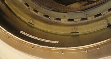
- Reinstall the axial stop assembly at the patient end of the magnet, making sure the gradient coil is making contact with the patient end axial stops.
- Slowly lower the gradient coil onto the gradient mounting pads.
- Release pressure on the beam, so the coil is supported by the two pads.
Figure 40. Axial stop 1 M10 x 30 mm brass bolt 2 M10 brass nut 3 Rear axial stop 4 Axial stop stud
Install the six wedges with one M10 x 24 mm washer and one brass M10 x 35 mm hex head bolt per wedge on the patient end of the magnet flange in the order shown in Figure 18.Notice - Note: Observe the following:Reinstall the busbar cables to the new gradient coil, placing a new Nord-Lock washer over each M12 SmartBolt prior to torquing in place.
- Always use the new Nord-Lock washers that come with the FRU package. Do not reuse the old Nord-Lock washers and stainless steel flanged nuts.
- Nord-Lock washers consist of two pieces, which are generally glued together. Always use a complete set with two pieces joined together in correct orientation. Do not use a separated single piece.
Figure 41. Nord-Lock washer configuration 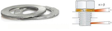
- Inspect the gradient coil terminal surface for contaminants or gouges, and clean the surface before installing the busbar terminal.
Notice Figure 42. SmartBolt 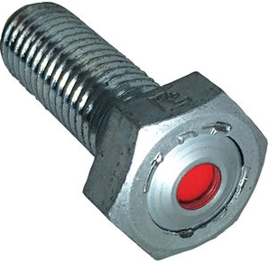
DANGER
Set the torque wrench to 59 ft-lb (80 N m), and install the 17 mm socket onto the extension.Notice Note: Make sure that the arrow on the torque wrench is visible. If the arrow is not visible, the torque wrench will not click when the proper torque is reached.Figure 43. Arrow on the nonmagnetic torque wrench 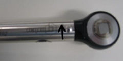
- Check the SmartBolt when the torque wrench reaches its break point. If the indicator is still red, then the bolt has not been seated properly; replace the bolt. If the indicator is black, then you have completed the torquing process.
Figure 44. SmartBolt indicators 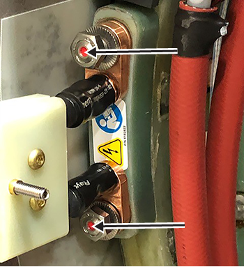
- Reinstall the safety cover.
- Make sure the flame-retardant cloth is folded out around the edges of the safety cover.
Figure 45. Aligning the safety cover with the inside stud 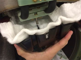
- Install the safety cover over Terminals 1 and 2, and align the cover with the 1/4 inch inside stud on the busbar clamp.
Figure 46. Cable terminals for Y and XZ busbars 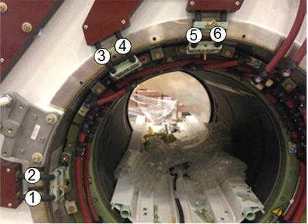
1 Y busbar cable terminal 2 Y busbar cable terminal 3 XZ busbar cable terminal 4 XZ busbar cable terminal 5 XZ busbar cable terminal 6 XZ busbar cable terminal
Rotate the safety cover upward so both studs protrude through the cover.Notice Figure 47. Rotating the safety cover 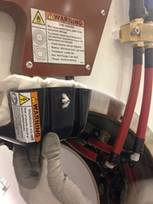 Note: Make sure that the flame-retardant white cloth is between the gradient coil FR4 terminal block and the safety cover with no gaps between the safety cover and the gradient coil.
- Make sure the flame-retardant cloth is folded out around the edges of the safety cover.
- To secure the safety cover:
- Shake the bottle, and apply one drop of Loctite 243 to either the threads on the stud or the nut.
Figure 48. Loctite on threads or nut 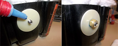
- Shake the bottle, and apply one drop of Loctite 243 to either the threads on the stud or the nut.
- To connect the XRMw coil manifold:
- Remove the copper block and hose assembly from the removed gradient coil, and replace the 165 mm (1) and 150 mm (2) hoses with pieces cut from the hose material provided in the replacement gradient kit.
Figure 49. Return outlet and supply inlet hoses 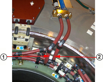
- Remove the copper block and hose assembly from the removed gradient coil, and replace the 165 mm (1) and 150 mm (2) hoses with pieces cut from the hose material provided in the replacement gradient kit.
Finalization
Procedure
Reinstall all passive shim trays into their proper slots. [The procedure for replacing shim trays is in the Magnet and Cryogen Manual for Passively Shimmed Magnets (5495018).]Warning