
- Discovery MR750w and SIGNA™ Architect T 3.0T System Service Methods
- 5690002-2EN Revision 4
- 00000018WIA30D5CE20GYZ
- id_131061403.2
- Nov 3, 2021 4:50:29 PM
B0 Drift Functional Check
Prerequisites
| Personnel requirements | |||
|---|---|---|---|
| Required persons | Preliminary requirements | Procedure | Finalization |
| 1 | - | 90 minutes | - |
| Tools and test equipment | |||
|---|---|---|---|
| Item | Quantity | Part number | Manufacturer |
| Body TLT Loader for 3.0T | 1 | 2360037 | - |
| Service Filler Panel | 2 | 5344577 | - |
| Required conditions |
|---|
|
All other applicable calibrations must be complete. |
|
Heat exchanger must be within operating limits. |
|
System must be idle for a minimum of 2 hours before functional check. |
About this task
This procedure can be performed using either a flat table or a curved table.
Using B0 Drift Tool
Procedure
- (For curved table) Install a service filler panel under both cradle top panels.
Figure 1. Service Filler Panel Installed on Curved Table 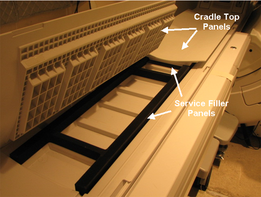
- (For flat table) Place the TLT phantom and sphere on the flat table. Position the phantom in the center of the cradle and center it on the PA coil. To achieve the best test measurement, the phantom must be located in the center (long direction) of the cradle (landmark the center of phantom at 1080 mm from Home Position).Note:
(For curved table) Place the TLT phantom directly on the cradle.
Note: This image is a representative example. Actual systems may vary.Figure 2. TLT Phantom and Sphere on Flat Table 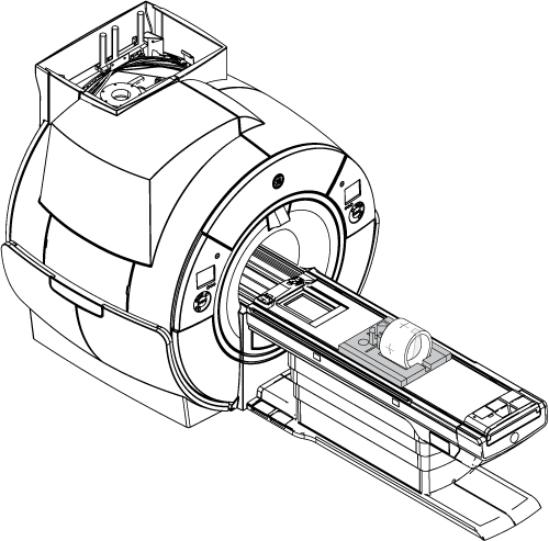
- Start the B0 Drift tool:
- (For non-proprietary service tools) From the Common Service Desktop, select . Select Click here to start this tool.
The B0 Drift window appears.
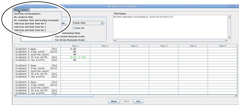
Figure 3. B0 Drift Window in Test Mode with X, Y, and Z Axes Highlighted 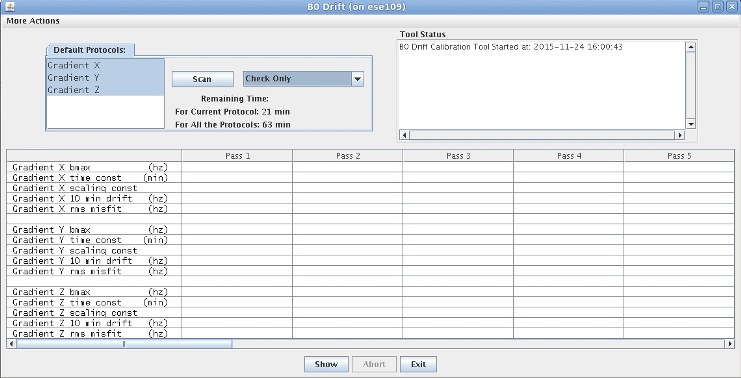
Additional Functions of B0 Drift Tool
About this task
-
Zero Out Cal Parameters: Zero out the calibration file. It can be executed for one axis or all three axes.
-
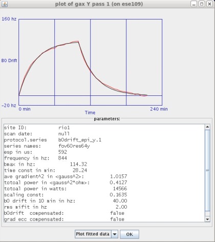
Re-Analysis Only: Re-analyze or view a previously executed pass (existing data).
-
Re-Calculate Time and Scaling Constants: Use existing data to put back into the calibration file of the system. If you want to use existing data:
-
First, run Re-Analysis Only.
-
Select Re-Calculate Time and Scaling Constants.
-
In the new dialog window, select the axis that you want to change.
-
Select Re-Calculate Time and Scaling Constants and click Apply.
-
-
Add Scan and Wait Time for x/y/z axis: Do not use.
Finalization
Finalization
Remove service equipment, phantom, and head coils.
(For curved table) Remove service filler panels from each cradle top panel.