
- Discovery MR750w and SIGNA™ Architect T 3.0T System Service Methods
- 5690002-2EN Revision 4
- 00000018WIA3068BE20GYZ
- id_131063864.7
- Jul 13, 2021 6:11:54 PM
GEM replacements
GEM PA Coil or PA Filler Replacement
Follow this procedure to replace either the PA coil or PA filler.
Personnel Requirements
| Required Persons | Procedure Timing |
| 1 | 60 minutes |
Preliminary Requirements
Tools and Test Equipment
| Item | Qty |
| Flat-head screwdriver | 1 |
| Phillips-head screwdriver | 1 |
Parts
| Item | FRU Part Number | Qty | |
| 1.5T GEM PA coil | See FRU manual | 1 | |
| 3.0T GEM PA coil | 1 | ||
| 1.5T GEM PA filler | 1 | ||
| 3.0T GEM PA filler | 1 | ||
Procedure
| Notice | |
|---|---|
-
Remove the patient table from the magnet room, and lock the wheels on the table to prevent it from moving.
-
Locate the front of the patient table and the buttons. Push the button labeled 1 (in the illustration below) down toward the floor while pushing the button labeled 2 in.
Figure 1. Location of Table Buttons 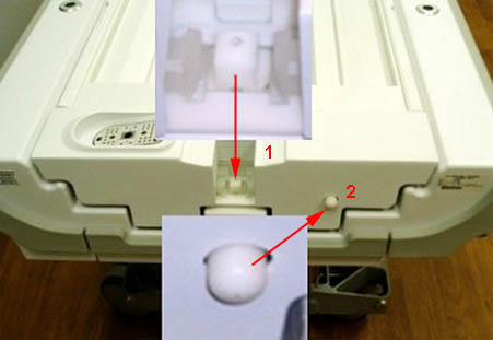
-
Continue pushing in both buttons, and pull the cradle toward you until a click is heard and the cradle stops moving.
Figure 2. Pulling Cradle 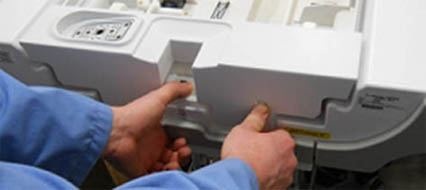
-
Lift up on the center of the cradle, and pull the cradle toward you until the rear of the cradle clears the cradle guide rails.
Figure 3. Cradle Guide Rails 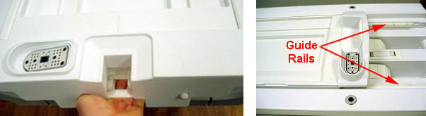
-
Locate the rear of the cradle, remove the two inner screws with a Phillips screwdriver, and lift the plastic cradle cover out.
Figure 4. Removing Cradle Cover 
-
Lift the rear of the cradle, and remove the screw on the left and right side of the cradle.
Figure 5. Screw Location Cradle (Right Side Shown) 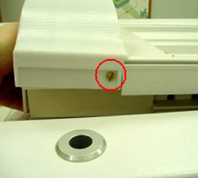
-
Remove the upper two screws on the plastic pieces and rotate them as shown.
Figure 6. Screws and Plastic Pieces 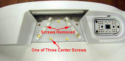
-
Remove the three center screws. Lift and remove the rear section of the cover from the cradle.
Figure 7. Rear Section of Cradle Cover Removed 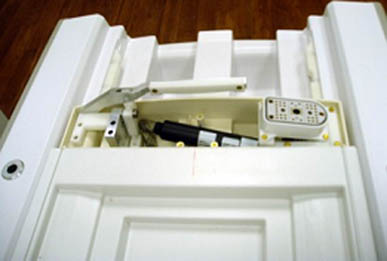
-
Remove the left and right strap rails by sliding each from the middle and front sections of the cradle. (To make it easier to remove the strap rails, release the cradle from the guide rails and lift it toward the back of the table.)
Figure 8. Removing Left and Right Strap Rails 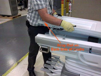
-
Lift up on the on the cradle and push it back into position.
Notice -
Remove the cradle cover by lifting up and sliding the cover out from the front of the cradle.
Figure 9. Removing Cradle Cover 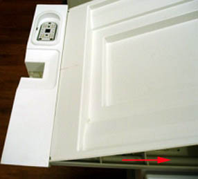
-
Remove the shoulder screw and the 4 screws securing the 2 end ribs to the cradle (one near the front and one near the rear section of the cradle.)
Figure 10. Removing Shoulder Screw 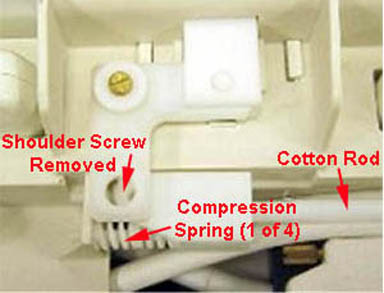
Figure 11. Removing Screws on End Rib (2 Places) 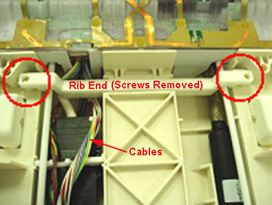
-
Remove the six screws from the PA coil or PA filler. Carefully move the filler enough to clear access to the cotton rod. Be careful not to strain the attached cables while moving the filler.
Figure 12. Removing Screws on PA Coil or Filler 
Figure 13. Moving the PA Coil or PA Filler 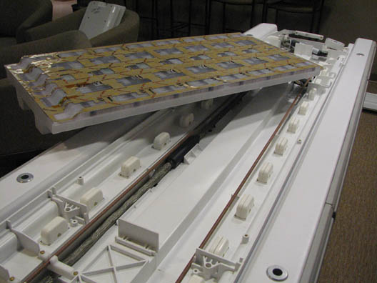
-
Flex the cotton rod at the middle section of the cradle. Carefully slide it out from the rear section of the cradle.
Be careful not to break the 2 pins at the end of the cotton rod or lose any of the 4 compression springs. For more information about safe handling of the cotton rod, see Cotton Rod Replacement.
-
After the cotton rod is removed from the cradle, restore the PA coil or PA filler to its location in the center section of the cradle.
-
Unplug all system cables from the PA coil or PA filler. Remove the coil or filler from the cradle.
-
Restore the cotton rod into the cradle, leaving it loose at the rear section of the cradle. Do not restore the shoulder screw at this point.
-
Place the replacement PA coil or PA filler into the cradle, and orient so the cables face the end of the table.
Figure 14. Table End Labeled Rear 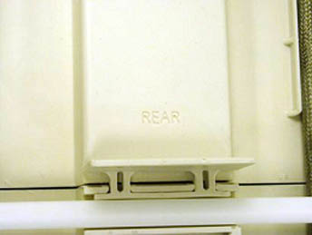
-
With the cotton rod loose (move it to one side), connect the cables from the new PA coil or PA filler to the cables in the table. (The PA filler has only the J4 cable.) Ensure the spacer bracket is properly oriented.
The PA coil or PA filler will rest on the side of the table while the cables are being connected.
Figure 15. Connecting PA Cables to Table Cables 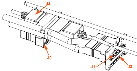
-
When all the cables are connected (with the PA coil or PA filler resting on the side of the table), restore the 4 compression springs to the 2 pins at the end of the cotton rod.
-
Flex the cotton rod at the middle section of the cradle and reconnect to the rear section of the cradle. Install the shoulder screw.
-
Place the new (replacement) PA coil or PA filler into the cradle and orient it so the cables face the end of the table (labeled REAR).
-
Install the 2 end ribs with 2 screws each as shown in Figure 11.
-
Secure the PA coil or PA filler to the table with six screws as shown in Figure 12.
Note:It may be necessary to use a screwdriver to perforate amber-tinted film over screw holes to permit reinstallation of screws to secure the coil. Do not remove film from the coil surface, because it prevents loose hardware from falling into the coil and causing damage to the internal electronic circuitry.
-
Place the cradle cover on the cradle, ensuring the front edge of the cover slides into the groove of the cradle’s front section, and lower the cover onto the cradle.
Figure 16. Replacing Cradle Cover 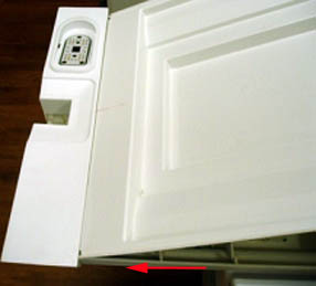
-
Locate the front of the patient table and the buttons. Push the button labeled 1 (in Figure 1) down toward the floor while pushing the button labeled 2 in.
-
Continue pushing in both buttons, and pull the cradle toward you until a click is heard and the cradle stops moving.
-
Lift up on the center of the cradle, and pull the cradle toward you until the rear of the cradle clears the cradle guide rails.
-
Reinstall the left and right strap rails by sliding from the middle and back sections. Ensure there is no gap between the strap rails and the cradle front section.
Figure 17. Eliminating Gap between Strap Rails and Cradle 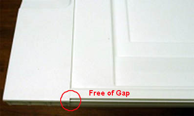
-
Reinstall the rear section cover housing, and secure it with the screws. Ensure the cradle cover slides into the groove of the cover housing.
Figure 18. Reinstalling Rear Cradle Cover 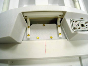
-
Lift the rear of the cradle, and reinstall the screws on the left and right side of the cradle.
-
Reinstall the last cover with the two inner screws.
-
Lift up on the on the cradle and push it back into position.
Figure 19. Positioning Cradle 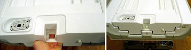
Finalization
Perform the following tests.
-
For replacement of the PA coil or PA filler: Run the dual drive quadrature toolDual drive quadrature tool to recalibrate the RF signal.
-
For replacement of the PA coil: Run the Multi-Coil Quality Assurance Tool to verify that the coil operates properly.
-
For replacement of the PA coil or PA filler: Run Doing a check scan.
AA Cable Replacement
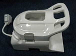
Follow this procedure to replace the system cable on the AA Coil. Before beginning this procedure, remove the coil from the magnet room. Wear an ESD wrist strap to avoid electrostatic discharge.
Personnel Requirements
| Required persons | Preliminary requirements | Procedure | Finalization |
|---|---|---|---|
| 1 | 45 minutes |
Preliminary Requirements
Tools and Test Equipment
| Item | Quantity | Effectivity | Part number | Manufacturer |
|---|---|---|---|---|
| Nonmagnetic Titanium Service Tool Kit, Large Set | 1 | - | 5112581 | - |
| ESD Strap | 1 | - |
Parts
| Item | FRU Part Number | Qty |
| AA System Cable | See FRU Manual | 1 |
| AA Coil | See FRU Manual | 1 |
Procedure
-
Remove the six screws securing the cover over the system cable.
Figure 20. Cover and Screws 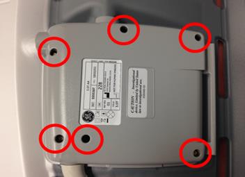
-
Locate the connector of the system cable. Pull up on the connector and remove the system cable from the housing.
Figure 21. System Cable Connector 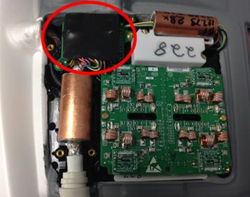
-
Insert new system cable in the housing. Ensure the flat portion of the strain relief is placed in the bottom housing.
Figure 22. Strain Relief Placement 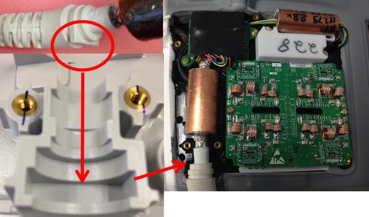
-
Ensure the serial number on the cover matches the serial number inside the coil. Place cover on the coil and ensure wires leading to the system cable connector are not pinched between the housings. Secure the cover to the coil with the screws removed in step one.
Figure 23. Serial Number 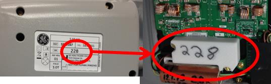
Finalization
Run the MCQA Tool to verify the AA Coil operates properly.
GEM Head Neck Unit (HNU) Cable Replacement
Follow this procedure to replace the system cable on the HNU coil.
Personnel Requirements
| Required Persons | Procedure Timing |
| 1 | 45 minutes |
Preliminary Requirements
Tools and Test Equipment
| Item | Qty |
| Flat-head screwdriver | 1 |
| Pliers | 1 pair |
| Side cutters | 1 pair |
Parts
| Item | FRU Part Number | Qty |
| 1.5T GEM HNU System Cable | See FRU manual | 1 |
| 3.0T GEM HNU System Cable | 1 |
Procedure
-
Remove the anterior section of the HNU coil if connected.
Figure 25. Anterior Section Removed 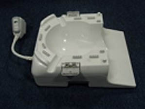
-
Position the posterior section of the coil to expose the bottom cover and screws.
-
Remove the 16 screws from the bottom cover of the posterior section, and segregate the four shorter screws from the other screws.
Figure 26. Location of Screws on Bottom Cover 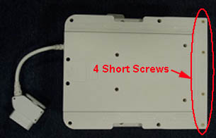
-
- Remove the RF connectors labeled J8, J2 and J11 by pulling each out in a horizontal direction.
Figure 27. Location of RF and Coil ID Connectors 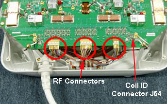
- Remove the single DC connector labeled J64, located in the bottom left corner, by using pliers and pulling straight up from the board.
Figure 28. Removing DC Wire Connector J64 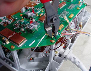
- Remove the twisted pair DC connector labeled J83 by pushing in on the clip and pulling the connector straight up from the board.
Figure 29. Location of DC Connector J83 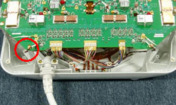
- Remove the coil ID connector labeled J54, located under the board in the lower right corner, by pushing in on the clip and pulling downward on the connector.
Figure 30. Location of Coil ID Connector J54 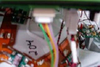
-
Use the side cutters to cut the zip tie.
Figure 31. Cutting Zip Tie 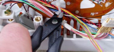
-
Remove the two screws holding the system cable to the clamp.
Figure 32. Removing Cable Clamp Screws 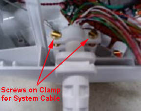
-
Place the new system cable on the HNU coil with the flat side of the strain relief facing up and the curved side facing down, and secure in the cable clamp with the screws just removed.
Figure 33. Flat Side of Strain Relief Facing Up 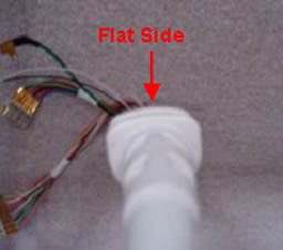
-
Reconnect the DC cable labeled J54 on the underside of the board, ensuring the clip is facing out prior to connecting. (A click will be heard when the connector is properly seated.)
-
Reconnect the single DC connector labeled J64.
Figure 34. Location of DC Connector J64 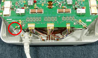
-
Reconnect the twisted pair DC connector labeled J83, ensuring the clip of the connector is facing out. (A click is heard when the connector is properly seated.)
-
Reconnect the RF connectors labeled J8, J2 and J11 to the correct locations on the board as shown in Figure 27, and use a zip tie to secure the cables in this location.
-
Replace the posterior cover on the HNU coil, ensuring the cables are not pinched when the cover is placed on the coil.
-
Secure the cover with the 16 screws removed earlier.
-
Ensure the shortest screws are located away from the system cable, as shown in Figure 26.
-
Finalization
Run the MCQA Tool to verify the HNU coil operates properly.
GEM PV Cable Replacement
Follow this procedure to replace the system cable on the PV coil.
Personnel Requirements
| Required Persons | Procedure Timing |
| 1 | 45 minutes |
Preliminary Requirements
Tools and Test Equipment
| Item | Qty |
| Flat-head screwdriver | 1 |
Parts
| Item | FRU Part Number | Qty |
| 1.5T GEM PV system cable | See FRU manual | 1 |
| 3.0T GEM PV system cable with balun | 1 | |
| 3.0T GEM PV system cable without balun | 1 |
Procedure
- Position the PV coil to expose the screws on the posterior section of the coil, and remove the seven screws closest to the system cable. (Do not remove the eight screws opposite of the system cable.)
Figure 35. PV Coil 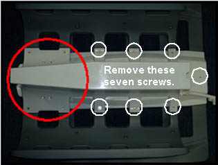
-
When removing the screw on the end, do not allow the latch catch to fall from the coil. Set it aside for use later in the procedure.
Figure 36. Latch Catch 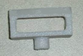
-
Rotate the PV coil to expose the anterior section of the coil. (The anterior cover should no longer be attached.)
-
Remove the DC connectors labeled J3 and J38 by pushing in on the clip and pulling the connectors straight up from the board.
Figure 37. DC Connectors J3 and J38 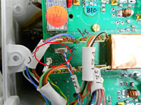
- Remove the RF connectors labeled J33, J34, J35, and J36 by pulling straight up from the board.
Figure 38. RF Connectors J33, J34, J35, and J36 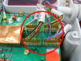
- Place the new system cable on the PV coil, ensuring that the flat side of the strain relief is facing down, and reconnect the RF connectors labeled J33, J34, J35, and J36.
Figure 39. Flat Side of Strain Relief Facing Down 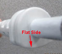 Note:For systems with the RRx receive chain, replace with the PV system coil without balun.
Figure 40. PV System Coil-Without Balun 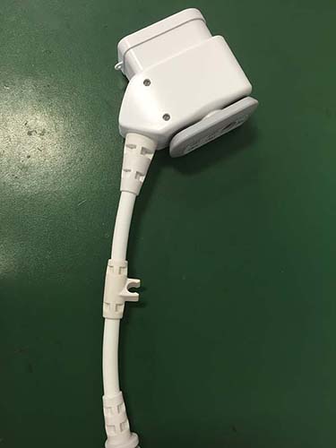
-
Reconnect the DC connectors labeled J3 and J38, ensuring they are properly oriented before plugging them in. (A click is heard when the connectors are properly seated.)
-
Reinstall the anterior cover on the PV coil and secure with the six of the seven screws removed earlier.
-
Reinstall the latch catch and the seventh screw on the anterior cover. The post of the latch catch fits into the anterior section of the coil and can be positioned in one direction.
Figure 41. Placement of Latch Catch Post 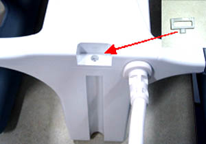
Finalization
Run the MCQA Tool to verify the PV coil operates properly.
GEM PV Latch Replacement
This procedure is used to replace the latch and latch catch on the PV coil.
Personnel Requirements
| Required Persons | Procedure Timing |
| 1 | 45 minutes |
Preliminary Requirements
Tools and Test Equipment
| Item | Qty |
| Flat-head screwdriver | 1 |
Parts
| Item | FRU Part Number | Qty |
| GEM PV Latch Kit | See FRU manual | 1 |
Procedure
-
Position the second station of the PV coil to expose the screws. Remove the 13 screws on the main portion and the 8 screws from the hinge area. Separate the 8 screws from the hinge area because they are a different size.
Figure 42. Location of Screws on Second Station 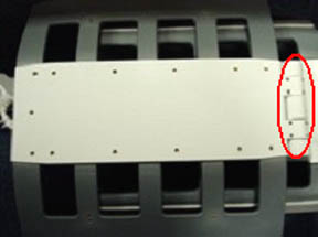 Note:
Note:Before lifting the second station, make sure to release the latch.
-
Remove the cover and locate the three latch screws and remove them.
Figure 43. Location of Latch Screws 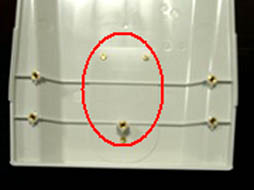
-
Reinstall new latch and secure with the three screws removed in the previous step.
-
Reinstall the cover and secure with the all the screws removed earlier. Remember that the screws on the hinge area are smaller than those on the rest of the cover.
-
Position the PV coil to expose the screws on the posterior section of the coil. Remove the end screw, and detach the latch catch from the coil.
Figure 44. Location of End Screw on Latch Catch 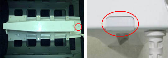
-
Install the new latch catch and secure with the end screw. (The post of the latch catch fits into the anterior of the coil and in one direction as shown in Figure 41.)
-
Run the MCQA Tool to verify the PV coil operates properly.