- Discovery MR750w and SIGNA™ Architect T 3.0T System Service Methods
- 5690002-2EN Revision 4
- 00000018WHA3014C6GYZ
- id_20018546.60
- Nov 3, 2021 6:28:32 PM
Configuring for LVShim
About this task
| Notice | |
|---|---|
The configuring process is different depending on the type of software you are using. Please select the appropriate procedure for configuring for LVShim.
Configuring for LVShim for systems running DV26.0 or earlier
About this task
Procedure
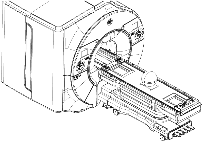
- Set up and align the LVShim phantom. Align the phantom so that:
- The phantom’s seam is oriented perpendicular to the table.
- The phantom’s z-axis is along the length of the cradle.
- The phantom is centered left to right with respect to the cradle top.
Note: This image is a representative example. Actual systems may vary.Figure 1. Placing the LVShim phantom on the patient table 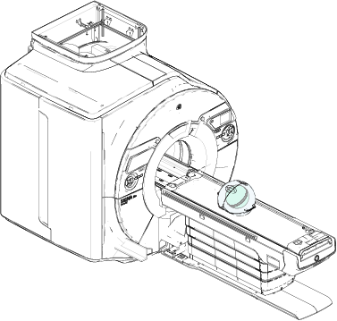
Configuring for LVShim for systems running DV29.1 or later
About this task
Procedure
- (For curved tables) Install a service filler panel under both cradle top panels.
Figure 2. Installing service filler panels on curved table 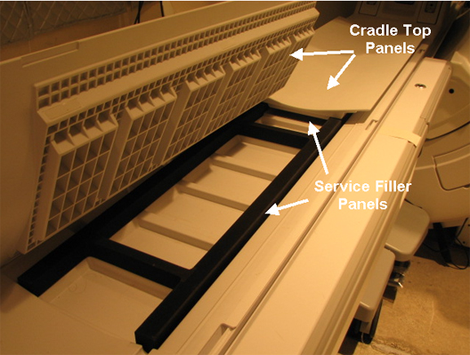
- Put the sphere on the pad with the strap (in the groove) in the orientation shown below, making sure the laser lights are cross-centered on the sphere and phantom pad.
Figure 3. Sphere phantom position Note: This image is a representative example. Actual systems may vary.