
- SIGNA MR355 / SIGNA MR360
- Service Manual
- 5856356-3EN Revision 5.0
- Basic Service Documentation. Copyright General Electric Company.
- 00000018WIA306AAF20GYZ
- id_131071711.9
- Mar 19, 2020 6:17:59 AM
System Gain Body Calibration
Prerequisites
| Required persons | Preliminary requirements | Procedure | Finalization |
|---|---|---|---|
| 1 | 10 minutes | 20 minutes | 10 minutes |
| ||||||||
| Condition | Reference | Effectivity |
|---|---|---|
|
Signa software is fully operational. | - | - |
|
Gradient Calibration is completed. | - | - |
|
No image artifacts are present. | - | - |
|
System is set to the English language. | - | - |
System Gain Body
Procedure
- For systems with the new Split-Top Head Coil, position the SNR
Sphere in the head loader as shown. Fasten the strap to the top of
the head load to secure the SNR Sphere in the loader.
Figure 1. Positioning SNR Sphere in Head Loader 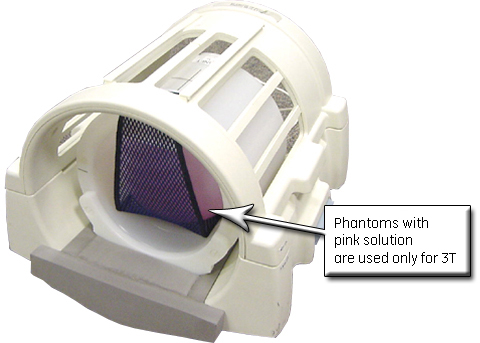
- Position the Head Loader on top of the Head TLT Loader Holder
in the head coil (shown below) so the loader is centered and the loader
axial mark is at the center of the head coil window.
Figure 2. Landmarking Head SNR Sphere 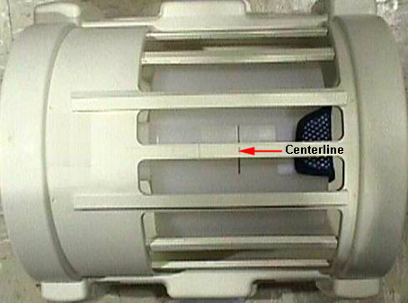
- Place the SPT Body Loader and Body Sphere after the head coil
as shown.
Figure 3. Phantom Setup 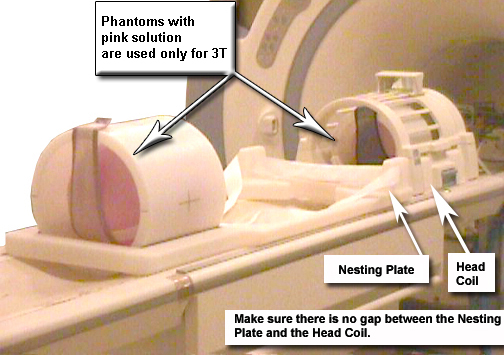
- Go to the CSD and start the Service Browser if not already running.
Select the Calibration icon
and select System Gain Calibration.
Figure 4. Starting System Gain Calibration 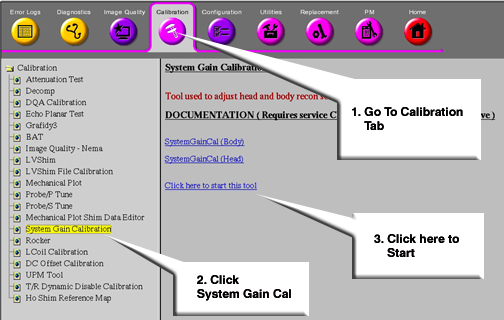
- In the System Gain Calibration tool, type 2 and press Enter for Auto Mode.
Figure 5. Starting System Gain Calibration in Auto Mode 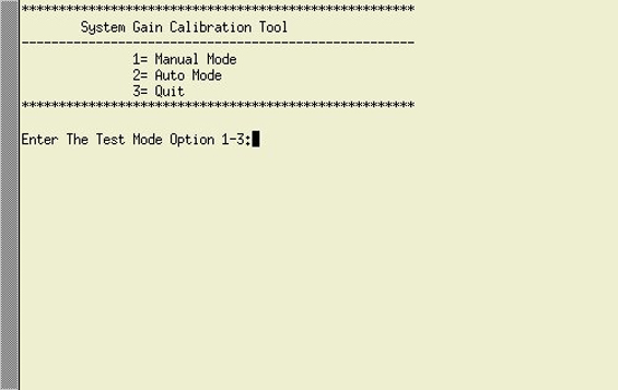
- In the next window, select option 2 and
press Enter for Body Mode calibration.
Figure 6. Selecting Body Mode Calibration 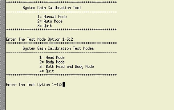
When testing is completed, one of two messages will display:
-
One will indicate the calibration is done and no adjustments are required.
-
The other message will ask if the new Recon Scale Factor should be saved. Type Y and press Enter to save the new calibration file.
Figure 7. Calibration Output 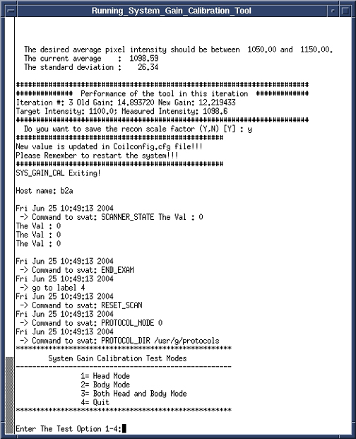
-
Finalization
Procedure
- Proceed to System Gain Head Calibration if required.
- Reboot the system.
- Remove all phantoms from the system, and perform a check scan to ensure system operation.