
- SIGNA MR355 / SIGNA MR360
- Service Manual
- 5856356-3EN Revision 5.0
- Basic Service Documentation. Copyright General Electric Company.
- 00000018WIA309A2F20GYZ
- id_131061123.0
- Aug 29, 2019 1:55:14 AM
Express Coil: Posterior Array Coil Replacement with removing Fixed Table
Prerequisites
| Required persons | Preliminary requirements | Procedure | Finalization |
|---|---|---|---|
| 2 | 0 minutes | 90 minutes | 0 minutes |
| Item | Quantity | Effectivity | Part number | Manufacturer |
|---|---|---|---|---|
| 1/8” and 1/4” Flathead Screwdrivers | 1 | - | - | - |
| ||||
About this task
This instruction provides procedure to disassemble and assembly cradle from tabletop on the SV fixed table.
Remove Fixed Table
Procedure
Remove FRP bottom covers of Fixed Table.Notice - Remove the Rubber cap and then screws of the FRP bottom cover
on the near the Gantry end of the Table.
Figure 1. FRP Cover1 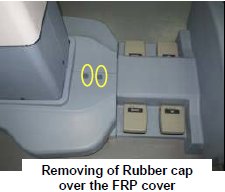
- Similarly remove the cap and screws of the FRP bottom cover
on the rear end of the Table.
Figure 2. FRP Cover2 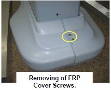
- Remove the right Bottom FRP Cover. Similarly remove the left
Bottom FRP cover on the other side
Figure 3. FRP Cover3 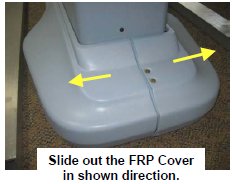
- Now remove the Dock FRP Cover Locking screws and then the Dock
FRP cover carefully.
Figure 4. FRP Cover4 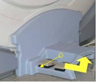
- Remove the Rubber cap and then screws of the FRP bottom cover
on the near the Gantry end of the Table.
- Disconnect cables.
- Disconnect the Sensor cable and Actuator Power supply cable
from the Power supply extension cable from Control box.
Figure 5. Disconnect cable 1 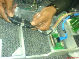
- Disconnect the Earthing cables from the Dock Frame.
Figure 6. Disconnect cable 2 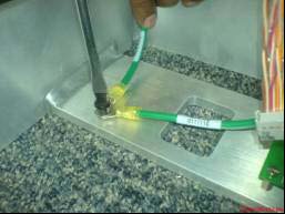
- Disconnect the Control Board Cable-2 (TEB Cable) Assembly from
the connector box.
Figure 7. Disconnect cable 3 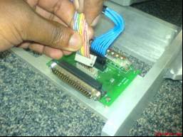
- Disconnect the Control Board Cable (TEB Cable) Assembly from
the connector box.
Figure 8. Disconnect cable 4 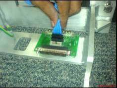
- Disconnect the Sensor cable and Actuator Power supply cable
from the Power supply extension cable from Control box.
- Remove the screws and nuts connecting the Table and the Dock
frame.
Figure 9. Dock Frame 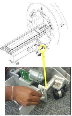
- Loosen four Leveling pads.
Figure 10. Loosen four Leveling pads 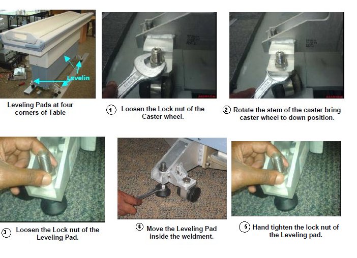
Cradle Disassembly Procedure:
Procedure
- Press White Delrin in one hand & pull the cradle out by
holding at front cradle section groove.
Figure 11. Cradle Disassembly 1 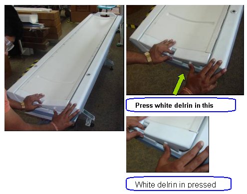
- Press the White delirin & simultaneously pull cradle out
about 20mm from tabletop.
Figure 12. Cradle Disassembly 2 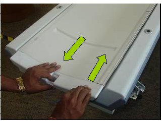
- Pull cradle out about 450mm from tabletop.
Figure 13. Cradle Disassembly 3 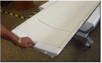
- On the other end, cradle will be out of tabletop side guide.
Figure 14. Cradle Disassembly 4 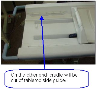
- Lift the cradle at the handle by 1 hand and use the other hand
to insert the foam
Figure 15. Cradle Disassembly 5 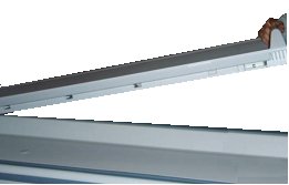
Figure 16. Cradle Disassembly 6 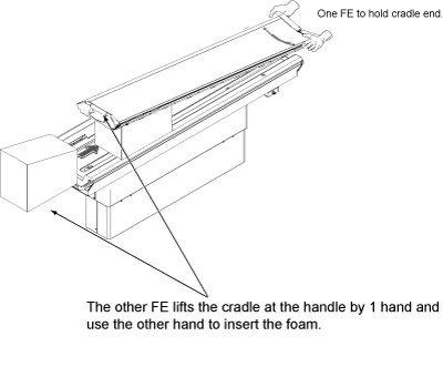 Note:
Note:Foam is stored in Cart during installation.
Figure 17. Foam Location 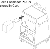
Access to the Connectors below the Cradle.Notice Figure 18. Cradle Disassembly 7 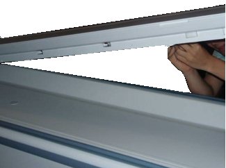
-
If there is no cable clamp: Remove
RF & DC connector from the socket mounted on the cradle:
Figure 19. Cradle Disassembly 8 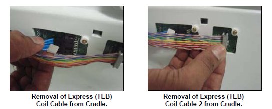
- Remove two M3 screw with the help of flat screwdriver and remove
cable track fixed on the cradle.
Figure 20. Cradle Disassembly 9 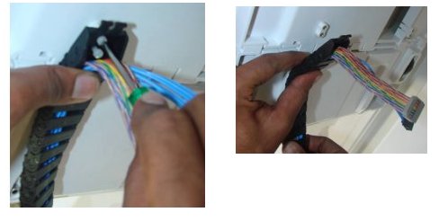
-
If there is cable clamp: Remove RF
& DC connector from the socket mounted on the cradle:
Figure 21. Cradle Disassembly 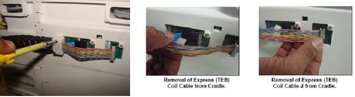
- Remove two M3 screw with the help of flat screwdriver and remove
cable track and Clamp Top fixed on the cradle:
Figure 22. Cradle Disassembly 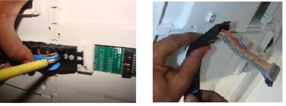
- Lift the cradle by both hand and place cradle on flat surface.
Figure 23. Cradle Lifting 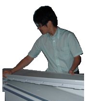
Cradle Assembly procedure:
About this task
Procedure
- Lift the new cradle and put it back onto the Table. One person
needs to sustain the cradle head end.
Figure 24. Cradle Assembly 2 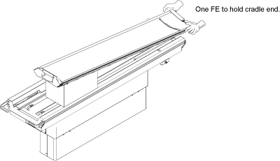
Replacement procedure for Revised RF Cable, DC Cable and DC Cable clamp assy.Notice Get below mentioned FRU part as per replacement requirement
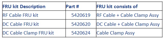
Figure 25. RF Cable FRU kit 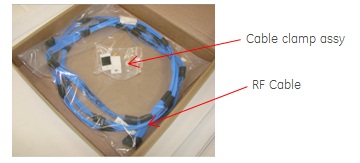
Figure 26. DC Cable FRU kit 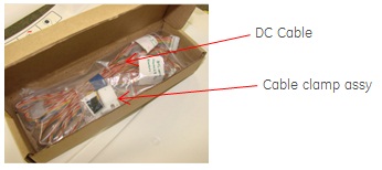
Figure 27. DC Cable Clamp FRU kit 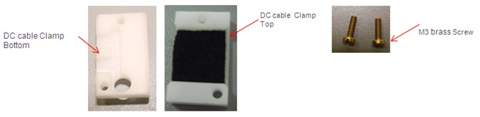
- Assemble DC cable Clamp bottom to Cable track end link.
Figure 28. Assembly DC Cable clamp 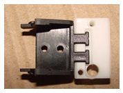
- Fasten these parts to cradle section with M3 screw.
Figure 29. Fasten DC Cable clamp 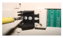
- Connect RF Cable and DC cable to cradle board, ensure both
the cable are placed flat one over the other.
Figure 30. Connnect RF Cable and DC Cable to cradle board 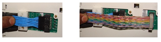
- Snap the Cable track along with RF Cable and DC cable to Cable
track end link.
Figure 31. Snap the cable track 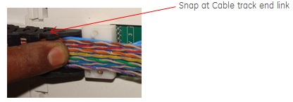
- Assemble DC cable Clamp top to DC cable Clamp bottom with M3
screw.
Figure 32. Assemble DC Cable clamp 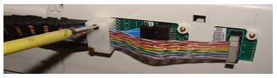
- Push back the cradle into the table top.
Figure 33. Cradle Assembly 4 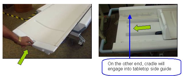
- Push back the cradle until it locks into table top. Now cradle
is secured into the tabletop.
Figure 34. Cradle Assembly 5 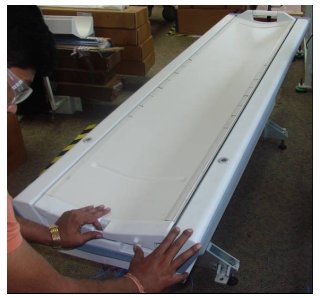
Finalization
Procedure
- Turn On the System Power. Refer to Lockout / Tagout for System Cabinet PDU Main Breaker.
- Perform Express Coil MCQA Test .