
- SIGNA MR355 / SIGNA MR360
- Service Manual
- 5856356-3EN Revision 5.0
- Basic Service Documentation. Copyright General Electric Company.
- 00000018WIA300BDF20GYZ
- id_131075153.0
- Aug 29, 2019 1:54:57 AM
Express Coil MCQA Test
Prerequisites
| Required persons | Preliminary requirements | Procedure | Finalization |
|---|---|---|---|
| 1 | 0 minutes | 30 minutes | 0 minutes |
| Item | Quantity | Effectivity | Part number | Manufacturer |
|---|---|---|---|---|
| TL UNIFIED PHANTOM | 2 | - |
5343347 | - |
| LARGE CYLINDRICAL UNIFIED PHANTOM | 1 | - |
5342679 | - |
| HNU Phantom Positioner | 1 | - |
5344844 | - |
| HNU Pad | 1 | - |
5343909 | - |
| AA Strap | 2 | - |
5344672 and 5344673 | - |
| Condition | Reference | Effectivity |
|---|---|---|
|
The appropriate coil configuration file must be installed to run this tool. | - | - |
|
If installing the coil for the first time in a system, please refer to Auto Coil Install . | - | - |
HNA Coil/PA Coil Check
Procedure
- Connect the HNA cable as shown inFigure 1.
Figure 1. Connecting the HNA Coil 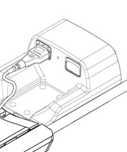
- Position the HNA and the phantoms as shown in Figure 2 and Figure 3. Make sure to use the phantom positioner and that the HNU pad is
underneath the phantoms.
Figure 2. Positioning the Phantom and the HNA 1 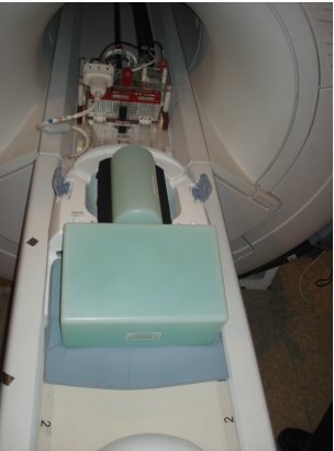
Figure 3. Positioning the Phantom and the HNA 2 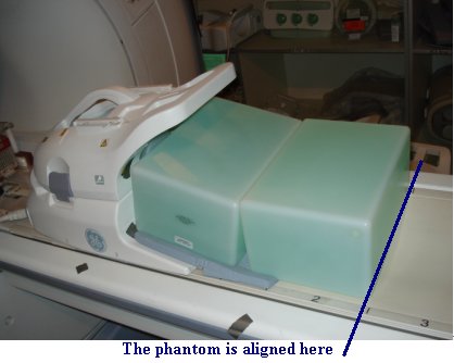
- Landmark on the HNA coil marking as shown in Figure 4
Figure 4. Landmarking Coil 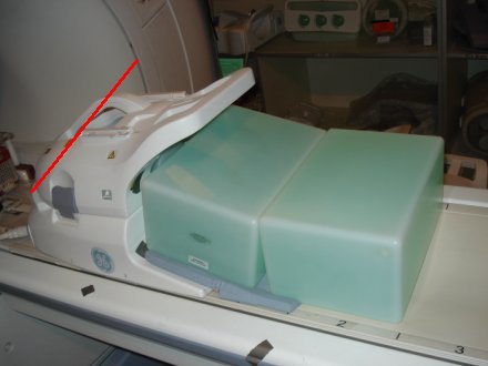
- Remove the anterior part from HNA coil, connect the HNA adapter,
keep the phantom set as same as before, as shown in Figure 5.
Figure 5. Positioning the Phantom and the HNA adapter 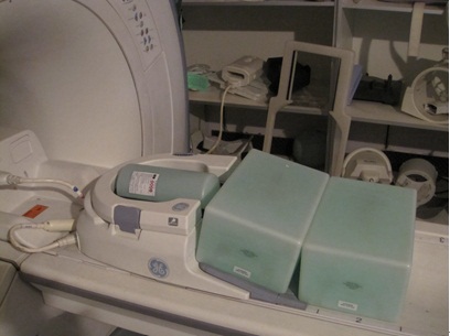
- Landmark on the center of blue latch as show inFigure 6.
Figure 6. Landmarking Coil 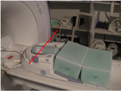
AA Coil/PA Coil Check
Procedure
- Connect the AA cable as shown in Figure 7.
Figure 7. Connecting the AA Coil - Position the Phantoms on the cradle between marker 3 and marker
4. Make sure that the space between the phantoms is aligned with the
line between marker 3 and marker 4. Place the AA coil on top of the
phantoms. Center it as shown in Figure 8.
Figure 8. Positioning the Phantom and the AA Coil 1 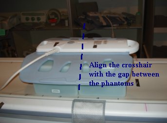
Figure 9. Positioning the Phantom and the AA Coil 2 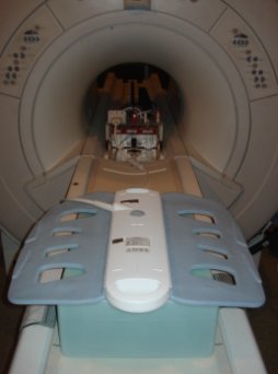
- Wrap the strap as shown in Figure 10.
Figure 10. Wrapping the coil 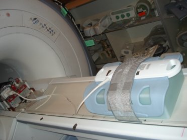
- Landmark on the AA coil marking as shown in Figure 11.
Figure 11. Landmarking Coil 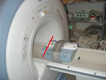
Finalization
Finalization
No finalization steps.