
- SIGNA MR355 / SIGNA MR360
- Service Manual
- 5856356-3EN Revision 5.0
- Basic Service Documentation. Copyright General Electric Company.
- 00000018WIA302E0F20GYZ
- id_131068584.0
- Mar 23, 2020 2:46:14 PM
1.5T 8-Channel Body Array Coil Setup for MCQA Test
Prerequisites
| Required persons | Preliminary requirements | Procedure | Finalization |
|---|---|---|---|
| 1 | Not Applicable | 15 minutes | Not Applicable |
| Item | Quantity | Effectivity | Part number | Manufacturer |
|---|---|---|---|---|
| 8-Channel Body Array Legacy Phantom Kit, Torso Coil,1.5T | 1 | Legacy Phantom Set |
2377425-3 | - |
| TL Unified Phantom Set | 2 | Unified Phantom Set |
5343347 | - |
| ||||
| Condition | Reference | Effectivity |
|---|---|---|
|
For HDe, HDx, and HDxt, the following coil configuration names must be installed to run this tool: HD BodyArray_serv, HD_BodyArrayLserv, and HD_BodyArrayRserv. | - | - |
|
For Discovery MR450 and Optima MR450w, the following coil configuration names must be installed to run this tool: 8Ch Body Upper, and 8Ch Body Lower. | - | - |
About this task
Follow this process to prepare for the automated SNR test using the 1.5T HD Body Array Coil by GE/USAI (M3335MC).
Note:
Coils do not ship with phantoms. Phantoms come in a unified phantom set with the MR system.
Legacy Phantom Procedure
Procedure
- Note:Position the coil in the cradle, connect the cable as shown in Figure 1.
If installing the coil for the first time in a system, please refer to Auto Coil Install.
Figure 1. Connecting the Coil 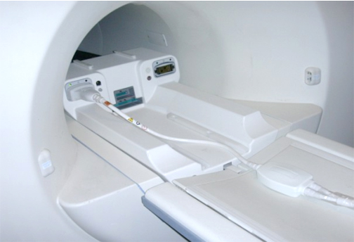
- Place a phantom between Posterior and Anterior parts of the
coil as shown in Figure 2.
Figure 2. Positioning Phantom 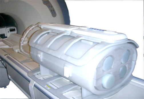
- Secure the coil over the phantom by strips as it shown in Figure 3.
Figure 3. Securing Coil Over Phantom 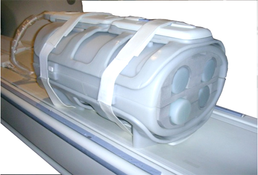
- Landmark the coil at the indicated line (arrows) as shown in Figure 4.
Figure 4. Landmarking the Coil 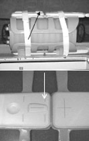
Unified Phantom Procedure
Procedure
- Place the posterior section of the coil on the table. See Figure 5.
Figure 5. Posterior Section of Coil on Table 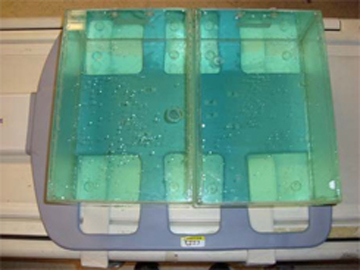
- Place the TL unified phantoms over the posterior section as
in Figure 5 such that the TL unified phantoms are well centered on both S/I
directions as shown in Figure 6 and R/L direction as shown in Figure 7.
Figure 6. Phantom Posterior Aligned on S/I Direction 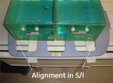
Figure 7. Phantom Posterior Aligned on R/L Direction 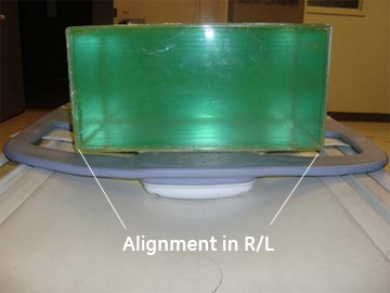
- Place the anterior section on the TL unified phantoms such that
the coil is well centered in both S/I and R/L directions with respect
to the phantom set as shown in Figure 8 and Figure 9.
Figure 8. Phantom Anterior Aligned on S/I Direction 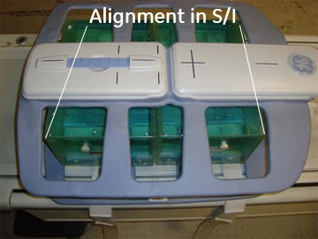
Figure 9. Phantom Anterior Aligned on R/L Direction 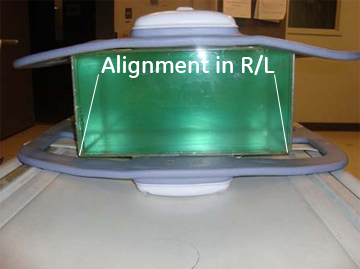
- Landmark the coil at the center cross mark as shown in Figure 10 and advance
to scan.
Figure 10. Landmark the Coil 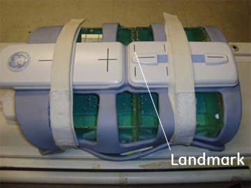
Finalization
Finalization
No finalization steps.