- id_12373703
- Version: 1.13
- Date: Jan 17, 2020 10:14:56 AM
Probe/SV Calibration and SNR Tests
Prerequisites
| Required persons | Preliminary requirements | Procedure | Finalization |
|---|---|---|---|
| 1 | Not Applicable | 30 minutes | Not Applicable |
| Item | Quantity | Effectivity | Part number | Manufacturer |
|---|---|---|---|---|
| MRS phantom without the loader is required for the Probe SNR and is used for the tuning process. | 1 | - |
2152220 |
- |
| 1.5T Split-Top Head Coil | 1 | - |
5328730 |
- |
Overview
The catalogs being used are:
-
Probe-P option
-
Probe-S option which includes Probe-P
-
Breast Spectroscopy
Overview
This material describes two separate hydrogen ONLY spectroscopy (Probe/SV) procedures:
-
Echo Peak Location calibration (automated Probe Tuning script)
-
Probe signal-to-noise ratio (SNR) performance test
Probe/SV Tuning Procedure (Echo Peak Location Calibration)
Setup
Procedure
- note:If there is an exam running, end the current exam (unless the exam was started with the “geservice” patient ID).
The Probe-S tuning procedure requires the site to have purchased catalog M3333WH. The following procedure does not run if the Probe-P option was purchased.
- Position the MRS phantom in the single channel head coil. Do NOT use the head loader with the MRS phantom. Use foam support pads for quick alignment to center the phantom in the head coil. Phantom centering (up/down/left/right/in/out) within 5 mm of the isocenter in all directions is important. Landmark on the center of the phantom.
- Run a 3-plane localizer to make sure the MRS phantom is properly centered. If necessary, perform an additional 3-plane localizer. After the phantom is centered, make sure the phantom remains stationary for at least 5 minutes before the start of any probe calibration scan. (This is to allow the fluid in the phantom to reach equilibrium and to minimize the effects of long-term eddy currents.)
Probe/S Tuning Procedure
Procedure
- Refer to Data Sheets for the tuning data sheet.
- Start the Probe/S Tune Tool:
- (For non-proprietary service tools) From the Common Service Desktop, select Calibration. Select Probe/S Tune from the Calibration menu, and select Click here to start this tool to start the procedure.
- At the Probe/S Tuning popup, press Enter to acknowledge. The calibration begins as shown below.
This is Probe-S Tuning Tool
Please landmark patient table as geservice
Press ENTER to start the tool or CTRL/C to stop the tool
Probe-S Cal Started
xshim= -2 yshim= 5 zshim= 2
APS: R1=13 R2=30 TG=187 CF=127762262
deltay_val: 0.253834
Y Axis Calibration completed Successfully
deltay_val: 0.523086
X Axis Calibration completed Successfully
deltaz_val: 0.174576
Z Axis Calibration completed Successfully
This message appears after the completion of the three axes:
Probe/S Tuning) completed successfully
Results are stored in /usr/g/caldir/probes_cal.log
Press [Enter] to quit -->
Press CtrlC to stop the tool.
This test takes about six minutes.
If probe calibration fails, re-run Grafidy, then try probe calibration again.
- To view the complete results:
- Select C Shell.
- Type: more /usr/g/caldir/probes_cal.log and press Enter.
- The specification criteria (absolute value) are:
-
Single delta parameter, < 0.8
-
Sum of all delta parameters, < 1.0
-
Probe/P Tuning Procedure
Procedure
- Refer to Data Sheets for the tuning data sheet.
- Position the phantom in the single channel head coil. Do NOT use the head loader with the MRS phantom. Use foam support pads for quick alignment to center the phantom in the head coil. Phantom centering (up/down/left/right/in/out) within 5 mm of the isocenter in all directions is important. Landmark on the center of the phantom.
- Run a 3-plane localizer to make sure the MRS phantom is properly centered. If necessary, run an additional 3-plane localizer. Once the phantom is centered, make sure the phantom remains stationary for at least 5 minutes before the start of any Probe calibration scan. (This is to allow the fluid in the phantom to reach equilibrium and to minimize the effects of long-term eddy currents.)
- Start the Probe/P Tune Tool.
- (For non-proprietary service tools) From the Common Service Desktop, select Calibration. Select Probe/P Tune from the Calibration menu, and select Click here to start this tool to start the procedure.
- At the Probe/P Tune popup, press Enter.
The calibration begins as shown below.
Probe-P Cal Started
xshim= -1 yshim= 5 zshim= 2
APS: R1=13 R2=30 TG=190 CF=127762262
deltay_val: -0.670430
Y Axis Calibration completed Successfully
deltax_val: 0.576271
X Axis Calibration completed Successfully
deltaz_val: -0.180328
Z Axis Calibration completed Successfully
This message appears after the completion of the three axes:
Probe/P Tuning completed successfully
Results are stored in /usr/g/caldir/probep_cal.log
Press [Enter] to quit -->
Press CtrlC to stop the tool.
This test takes about six minutes.
- To view the complete results (which do not contain auto pre-scan (APS) information):
- Select C Shell.
- Type: more /usr/g/caldir/probep_cal.log.
note:If the calibration log file is not available, perform a TPS reset and repeat these steps to view the log file.
- The specification criteria (absolute value) are:
-
Single delta parameter, < 0.8
-
Sum of all delta parameters, < 1.0
-
Probe/SV SNR Procedure
Use the MRS phantom (without the loader) for the signal-to-noise ratio (SNR) procedure. Enter the most visible number of the temperature strip as a Control Variable (tempC).
Probe-S SNR Procedure
Procedure
- note:Select Create new worklist
Use the MRS phantom for all SNR procedures. Position the MRS phantom centered on the head coil. Use foam padding as necessary to center the phantom in the head coil. Phantom centering (up/down/left/ right/in/out) is important. Run any head localizer to ensure the phantom is properly centered before beginning the Probe-S SNR procedure.
 .
.- Patient ID: geservice
- Name: probe snr
- Weight (lb.): 111
- Select Show All Protocols.
- Select Protocol Library option Service and select Other tab. Scroll through the list to the protocol Probe-S SNR. Select Series 1 and Accept, and then click Start Exam.
- Click the arrow next to the Scan Time indicator to expand the scan prescription area.
- Click the Advanced tab. Enter the temperature that is noted on the phantom.
- Click Save Rx.
- Click the arrow next to the Scan option, and then click Auto Prescan.
- Select Message Window, which is located in the bottom center of the scan desktop. Record R1, R2, TG, AX (and if present, record FWHM, WS Angle, WS%) on the Data Sheets. Close the window.
- Select Scan.
- Display the image, and record the displayed results of CR SNR on the Data Sheets for Probe-S SNR.
- note:Repeat Step 5 through Step 6 three times to get an average Probe-S SNR (C-SNR).
You must perform a minimum of three scans (back to back) to get an estimated average Probe-S SNR.
Probe-S SNR specification minimum is:
30.0 Cr SNR for 1.5T
Probe-P SNR Procedure
Procedure
- note:Select Create new worklist.
Use the MRS phantom for all SNR procedures. Center the MRS phantom on the head coil. Use foam padding as necessary to center the phantom in the head coil. Phantom centering (up/down/left/ right/in/out) is important. Run any head localizer to ensure the phantom is properly centered before beginning the Probe-P SNR procedure.
- Patient ID: geservice
- Name: probe snr
- Weight (lb.): 111
- Select Show All Protocols.
- Select Protocol Library option Service and select Other tab. Scroll through the list to the protocol Probe-P SNR. Select Series 1 and Accept, and then click Start Exam.
- Click the arrow next to the Scan Time indicator to expand the scan prescription area.
- Click the Advanced tab. Enter the temperature that is noted on the phantom.
- Click Save Rx.
- Click the arrow next to the Scan option, and then click Auto Prescan.
- Select Message Window, which is located in bottom center of the scan desktop. Record R1, R2, TG, AX (and if present, record FWHM, WS Angle, WS%) on the Data Sheets. Close the window.
- Select Scan.
- Display the image, and record the displayed results of CR SNR
on the Data Sheets of the Probe-S SNR.note:
You must perform a minimum of three scans (back to back) to get an estimated average Probe-S SNR.
- Repeat Step 5 through Step 6 three times to get an average Probe-P SNR (C-SNR).
Probe-P SNR specification minimum is:
60 Cr SNR for 1.5T
Troubleshooting
This section contains illustrations of probe SNR spectra, both incorrectly and correctly tuned, to show what a good spectrum looks like. During tuning or SNR troubleshooting, it may be necessary for a site to back up the original echoloc.dat file. This backup process requires renaming the file; otherwise, it will be overwritten during the tuning calibration. To get more information about the cause of an Auto-Water Suppression (AWS) failure, log the messages generated during the Probe APS. A site may be required to send probe SNR raw data to an expert for review. This section also explains the P raw file location process and how to transfer it.
Example SNR Spectra
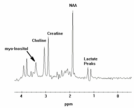
Errors in the probe tuning calibration procedure can introduce changes in the appearance of the resulting probe SNR spectra. This section contains example spectra from a Probe-P SNR protocol using the MRS phantom.
Procedure
-
Figure 1 shows a correctly tuned spectra. Pay particular attention to the
base (left and right) of the NAA (NA) peak; this is the largest peak
located at the center of the spectrum.
Figure 1. Correctly Tuned Probe SNR Spectra
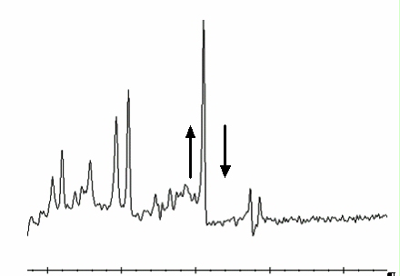
- Refer to Figure 2 and Figure 3 to view spectra with an uncalibrated tuning
parameter (a delta was offset + or - from the correct value by 0.5
units).
Figure 2. Incorrectly Tuned Probe SNR Spectra
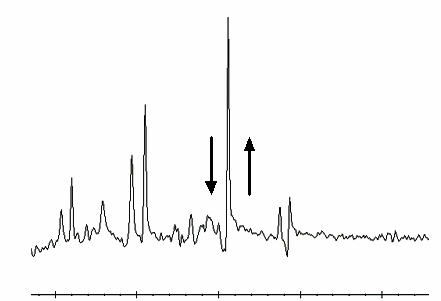
Figure 3. Incorrectly Tuned Probe SNR Spectra
- To perform probe tuning file and backup, follow these steps:
- At the MR Service Desktop, click C-Shell.
- At the prompt, enter the following:
su -
Password: operator
cd /usr/g/caldir Enter
cp echoloc.dat echoloc.bak1 Enter
note:It is possible that the customer changed the default password. If you cannot log in, contact the customer for the correct password.
- Close the C-shell.note:
The echoloc.dat file does not exist for initial software loads.
The actual files that contain the probe calibration values are in the caldir directory as probesfix.dat and probepfix.dat. The unlabeled values are deltax, deltay, and deltaz.
To get more information about the cause of an AWS failure, log the messages generated during the Probe APS.
Directory Creation
Procedure
- On the MR Service Desktop, click C Shell.
- Create a directory to hold the log file by entering the following:
cd /usr/g Enter
mkdir probe_data Enter
cd probe_data Enter.
- Log in to the MGD AGP and direct the output to a file and to the screen. Use the pipe symbol (|) on the keyboard where indicated below. Local is the lowercase “l” key.
- rlogin agp | tee agp_log Enter.
- Log in using the user name agp , then press Enter. When prompted, enter the password agpservice and press Enter.note:
It is possible that the customer changed the default password. If you cannot log in, contact the customer for the correct password.
At this point logging is running. DO NOT type anything in the AGP window. Watch the AGP messages appear on the screen; everything is logged to the file entered after the tee command (tee agp_log). This file is overwritten each time.
- Select the Rx Manager icon.
- Run Auto Prescan (APS).note:
No data appears in AGP_LX during APS.
- Select the Service Desktop Manager icon and use the scroll bar to review the log.
- When done, type logout in the AGP window. This disconnects the AGP from the C-shell. A message confirms the logout.
- To view the log file created, verify that the current directory is /usr/g/probe_data.
- Type more agp_log and press Enter.
- Close the C-shell when you are done.
- The log file can be sent to the OLC, or e-mailed to whomever the site is working with to resolve any problems.
P Raw Data File Location
During the troubleshooting process, the site may be required to identify the P raw data files generated when Probe SNR was performed. These files may be helpful in determining a reason for an SNR failure. This portion of the procedure should be performed after running a Probe SNR protocol to facilitate P raw file identification.
Procedure
- At the Service Desktop Manager, click C-Shell.
- At the prompt, enter the following:
cd /usr/g/mrraw Enter
ls -lt P*| head Enter
- The most recent P files are displayed. The most recent P files are displayed on the top of this list. Record the Probe raw data file (P####.7). The size of the P file is ~449584.
- Close the C-shell when finished.
Finalization
Finalization
Remove all service equipment from the system.