• SIGNA™ Hero 3.0T Service Methods
  • 5852800-8EN Revision 1.0
  • Object ID: 00000018WHA308C62GYZ
  • Topic ID: id_2001446 Version: 9.18
  • Date: Jul 13, 2021 4:05:21 PM

Doing UPM functional check for head channel

Procedure

  1. On the front of the exciter, set the RF ENB switch to the disabled (down) position.
  2. Reconnect the system body transmit cables J4 and J22.
  3. For head mode, disconnect J3 and connect the dummy load to J3.
    Note: Use the 7/16 Male to N Female adapter (included in the kit) to make this connection.
    Figure 1. Connect dummy load
  4. Set the RF enable switch to the On position.
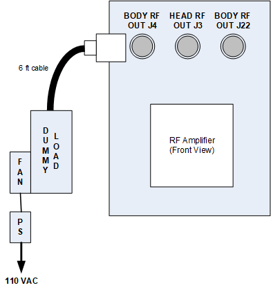
  5. Note: Be sure to check the resistance as noted in the Dummy load resistance check and setup procedure, prior to starting the UPM functional check.
    In the tool, make the following functional check selections:
    Figure 2. UPM functional check selections

    (For system running PX29.0 or earlier)
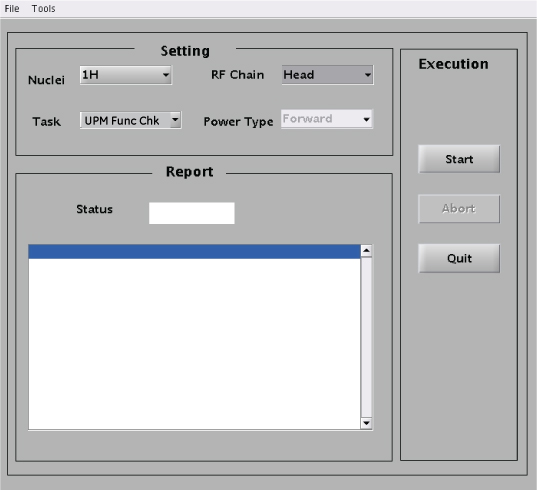
    SettingValue
    Nuclei1H
    TaskUPM Func Chk
    RF ChainHead
    Note: The Power Type drop-down menu is inactive for this step.
    Figure 3. RF Amp and Power Monitor (RAP) Tool functional check selections

    (For system running PX29.1 or later)
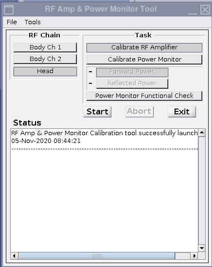
    SettingValue
    TaskPower Monitor Functional Check
    RF ChainHead
  6. Click Start.
  7. Click Yes when the prompt asks if the hardware setup is correct.
  8. Review the system prompts as they are shown during test execution.
    This functional check takes 2 to 3 minutes before any user interaction is required. Functional check tests include: 10-second average power check, RF inhibit test, and short-term average power fault host trip test.
  9. From the CSD, open the error log. Make sure the error log contains the message that the UPM has detected a power fault.
    • If the error is shown in the log, the functional test has passed. Click Yes on the dialog box.
  10. If the functional check passes, click Quit.
  11. If the test fails, go to UPM troubleshooting.