
- Discovery MR750 3.0T System Service Methods
- 5690009-2EN Revision 4
- 00000018WIA309D1130GYZ
- id_152710943.4
- Feb 7, 2022 10:19:00 PM
Leveling the patient table
Adjust the patient table for floor levelness and do a check of the caster height. If adjustment is required, level the patient table.
Prerequisites
| Personnel requirements | |||
|---|---|---|---|
| Required persons | Preliminary requirements | Procedure | Finalization |
| 1 | - | 60 minutes | 5 minutes |
| Tools and test equipment | ||||
|---|---|---|---|---|
| Item | Quantity | Effectivity | Part number | Manufacturer |
| Non-ferrous Level | 1 | - | - | - |
| Non-ferrous measuring device (ruler) | - | - | - | - |
| Non-magnetic Service Tool Kit | 1 | - |
5112581 | - |
| Safety | ||||
| ||||
About this task
Overview
The patient table is aligned vertically to the magnet by adjusting the caster height. However, the caster height must also be checked for uniform loading to ensure levelness.
Adjusting the patient table for floor levelness
Procedure
- Raise the patient table to a fully raised position. Using a nonferrous level, check levelness from front to back along the top right or left edge of the bridge, and from left to right across the front of the bridge.
Figure 1. Measuring levelness of patient table 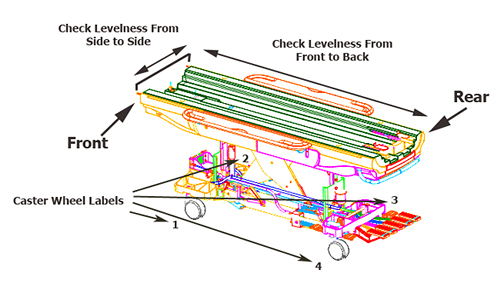 Note: Check that all casters are sharing the load equally by applying a small lifting force at each corner of the table, and watching the caster lift easily off the floor. If one caster or two diagonally-mounted casters seem to be unevenly loaded compared to the other casters, they will require adjustment.
Checking caster height adjustment
About this task
During installation, this procedure describes how to check the caster height (factory default) settings. If the patient table requires adjustment, continue to Leveling the patient table.
Procedure
- At each of the four caster wheel assemblies, measure the height from the floor to the bottom edge of the aluminum support casting.
Figure 2. Caster measurement 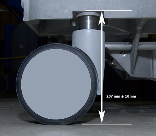
Leveling the patient table
About this task
Although all four casters look identical on the outside, there is one notable difference when observing each caster assembly inside the caster covers. The patient table front left caster is known as the steer lock wheel, and its caster assembly design has a triangle-shaped bracket that differs from the other three casters.
Procedure
For the caster that requires adjustment, remove the caster linkage pin using a 3/8 inch wrench.Notice Figure 3. Caster linkage pin 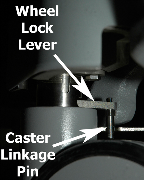
- Remove the collar bolt using an 7/16 inch wrench. (The illustration below shows a floor-level view looking at the right underside of the caster assembly; the same view for all four casters.)
Figure 4. Remove collar bolt 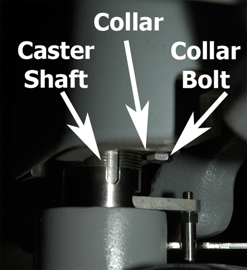
- Looking from the top down, move the wheel lock lever to the Full Lock position.
Figure 5. Wheel lock Lever positions 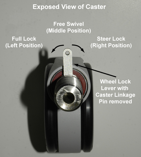
The wheel lock lever has three positions:
- Full Lock or Pivot Lock - Left position locks the caster so the patient table cannot move.
- Free Swivel - Middle position lets the caster move freely.
- Steer Lock - Right position locks the caster in place, but the wheels can turn.
Finalization
Procedure
- Dock the table.
- Make sure that the cradle release functions properly.
- Make sure that the cradle can move into the bore.