- Discovery MR750w and SIGNA™ Architect T 3.0T System Service Methods
- 5690002-2EN Revision 4
- 00000018WIA301E2A50GYZ
- id_20263681.7
- Jan 27, 2021 9:36:35 PM
Checking the patient handling system with the laser leveling tool
The proper alignment of the entire patient handling system is important for good image quality output from the GE MR scanners.
Prerequisites
| Personnel requirements | |||
|---|---|---|---|
| Required persons | Preliminary requirements | Procedure | Finalization |
| 1 | - | 55 minutes | - |
| Tools and test equipment | |||
|---|---|---|---|
| Item | Quantity | Part number | Manufacturer |
| PH Alignment and Magnet Leveling Kit | 1 | 5897979 | - |
| MR Patient Handling Alignment Macro Tool (Available from the Online Documentation Library) | 1 | DOC2372458 | - |
| Nonmagnetic Titanium Service Tool Kit, Small Set | 1 | 5113258 | - |
| Safety |
|---|
|
Before working in any GE Healthcare MR suite or performing any GE Healthcare service procedure, you must:
If you have any safety concerns at any time, do not begin work or immediately stop work and move to a safe location. Immediately contact your supervisor or site safety officer for instructions on how to proceed. |
About this task
If the check fails/adjustment is required, the FE can raise a separate SR and perform the adjustment during a different visit or during the same visit if there is adequate time. The procedure for making the adjustments is Adjusting the patient handling system with the laser leveling tool.
The patient handling alignment procedure is to be completed using the patient handling and magnet leveling tool kit (5897979) and the MR Patient Handling Alignment Macro Tool (DOC2372458).
Some of the tools included in the patient handling and magnet leveling tool kit (5897979) are specific to the magnet handling service procedures and will not be used during the patient handling alignment procedure. The below table lists the tools that will be used for the patient handling alignment procedure.
| GE part number | Quantity | Part description |
|---|---|---|
| 5831466 | 1 | Laser Level PLS 180R Z |
| 5897974 | 1 | Folding Ruler, 2 meters, FM-DELA.401.00 |
| 5829559 | 1 | Tripod, Vanguard Alta Pro 263AB 100 |
| 5829794 | 1 | Masking Tape, Pink, 0.94 Inch Wide |
| 5830232 | 1 | Horizontal Alignment Laser Target Tool |
| 5830232-2 | 1 | Horizontal Alignment Laser Target Tool - Tall |
| 5831978 | 2 | Vertical Alignment Tool |
| 5832719 | 1 | Table Bridge Boss Alignment Tool |
| 5346292 | 1 | Brass Height Tool |
The macro tool assists the user in identifying target values for aligning the GE MR scanner. The user captures the initial state of the scanner in the macro tool. The macro tool then calculates the ideal state of the scanner. The user adjusts the scanner based on the macro tool output. The user then captures the final state of the scanner in the macro tool.
| Warning | |
|---|---|
Procedure
- Fill in the table in the macro tool to begin the service procedure.
Figure 1. Sample entries in the tool 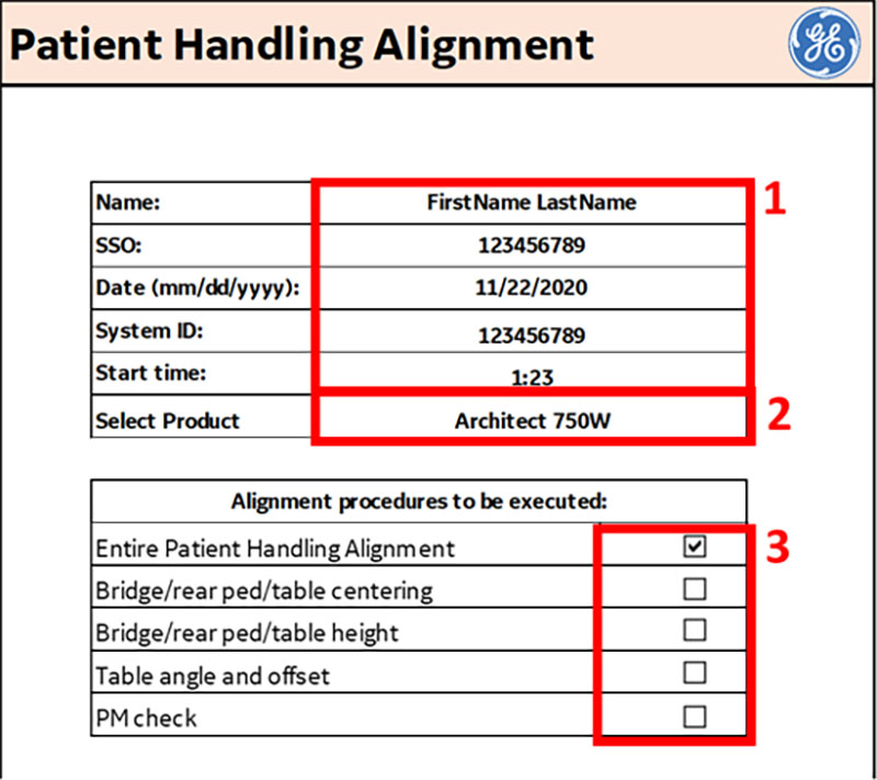
1 User information, system ID, and procedure start time Product Applicable procedures - Enter your first and last name, SSO, the current date (mm/dd/yyyy), system ID, and start time in the tool to begin the service procedure.
- Select the product the service procedure will be executed on.
- Select all of the patient handling procedures that apply. The macro tool has VBA code that shows and hides fields in the macro tool that are applicable to the service procedures selected.
Note: Follow legacy procedures for products that are not currently supported in the product selection list.
Tools overview
The patient handling alignment procedure is to be completed using the patient handling and magnet leveling tool kit (5897979) and the MR Patient Handling Alignment Macro Tool (DOC2372458).
Some of the tools included in the patient handling and magnet leveling tool kit (5897979) are specific to the magnet handling service procedures and will not be used during the patient handling alignment procedure. The below table lists the tools that will be used for the patient handling alignment procedure.
| GE part number | Quantity | Part description |
|---|---|---|
| 5831466 | 1 | Laser Level PLS 180R Z |
| 5897974 | 1 | Folding Ruler, 2 meters, FM-DELA.401.00 |
| 5829559 | 1 | Tripod, Vanguard Alta Pro 263AB 100 |
| 5829794 | 1 | Masking Tape, Pink, 0.94 Inch Wide |
| 5830232 | 1 | Horizontal Alignment Laser Target Tool |
| 5830232-2 | 1 | Horizontal Alignment Laser Target Tool - Tall |
| 5831978 | 2 | Vertical Alignment Tool |
| 5832719 | 1 | Table Bridge Boss Alignment Tool |
| 5346292 | 1 | Brass Height Tool |
The macro tool assists the user in identifying target values for aligning the GE MR scanner. The user captures the initial state of the scanner in the macro tool. The macro tool then calculates the ideal state of the scanner. The user adjusts the scanner based on the macro tool output. The user then captures the final state of the scanner in the macro tool.
| Warning | |
|---|---|
Checking the alignment of the bridge and rear pedestal (z-dir and x-dir)
Front end bell-bridge longitudinal (z-dir) offset
Procedure
- Measure the longitudinal (z-dir) distance between the front bridge surface to the front surface of the endbell cover on the left and right side of the bridge. This distance should be less than ± 3 mm on each side. This can be done using the folding ruler (5897974).Note: The folding ruler has a very small amount of ferrous content. Use caution when using it near the magnet.
Figure 2. Bridge to front surface of the endbell cover 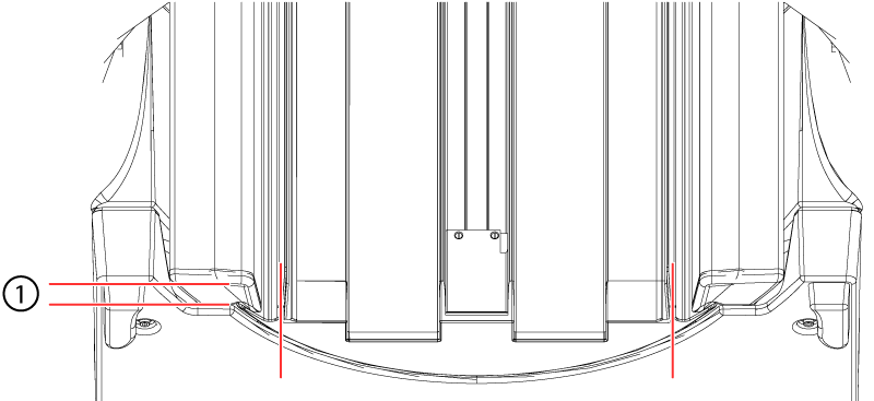
1 ± 3 mm - Record these values in the macro print-out for the left and right side in mm as they will be entered in the macro tool.
Figure 3. Sample front endbell-bridge longitudinal (z-dir) offset values in macro tool 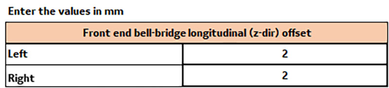
Bridge shoulder-body coil lateral (x-dir) gap front
About this task
Procedure
- Use the folding ruler to measure the gap between the bridge shoulder and body coil in the front and rear. The difference in measurement between the left and right side should be less than 2 mm.
Figure 4. Body coil gaps 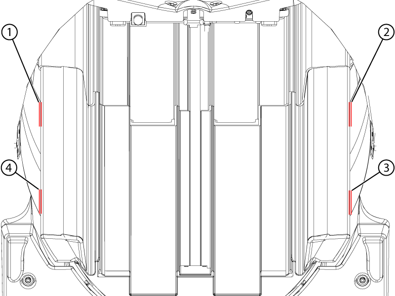
1 Rear left 2 Rear right 3 Front right 4 Front left Note: Measure from a consistent location from the filleted surface of the bridge shoulder to the body coil at the four locations. - Record the values in mm in the macro print-out as they will be entered in the macro tool. The tolerance for this is left-right <= ± 2 mm for front and rear of the bridge.
Figure 5. Sample bridge shoulder-body coil lateral (x-dir) gap values in macro tool 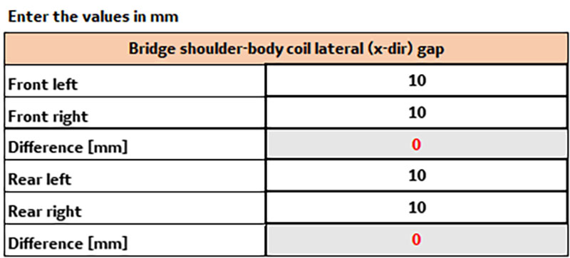
- Make sure the lower bridge support assembly is not touching the floor. Measure the distance using the folding ruler between the bottom of the lower bridge support assembly and floor should be >= 2 mm. This is to ensure that there is no vibration "short circuit".
Figure 6. Lower bridge support assembly alignment 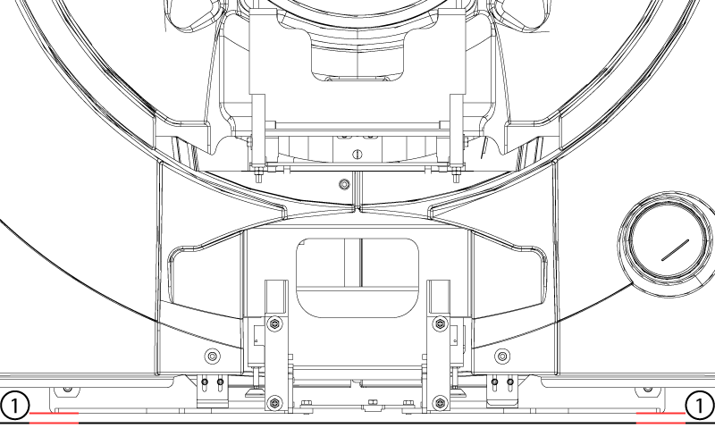
1 >= 2 mm Important: The laser measurements may not be within specifications after adjustments due to the existing magnet height and floor levelness. In such a case, try to adjust the system to as close as possible to the specifications without exceeding other specification limits.
Checking the alignment of the patient table angle (rotation about y-axis) and offset (x-dir)
Table 1 gap check
Procedure
- Record the measured values in the macro tool in millimeters. The gap should be no less than 12.6 mm (0.5 inches) and no greater than 25.4 mm (1 inch).
Figure 7. Sample table 1 gap check values in the macro tool 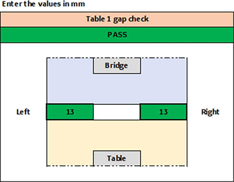
Table 1 angle and offset check
Procedure
- Record the values the vertical laser line strikes through on the horizontal scale on the short and tall targets. Make sure to capture if the number is positive or negative. The tolerance is ± 2 mm of the output values.
Figure 8. Sample table 1 angle and offset check values in the macro tool 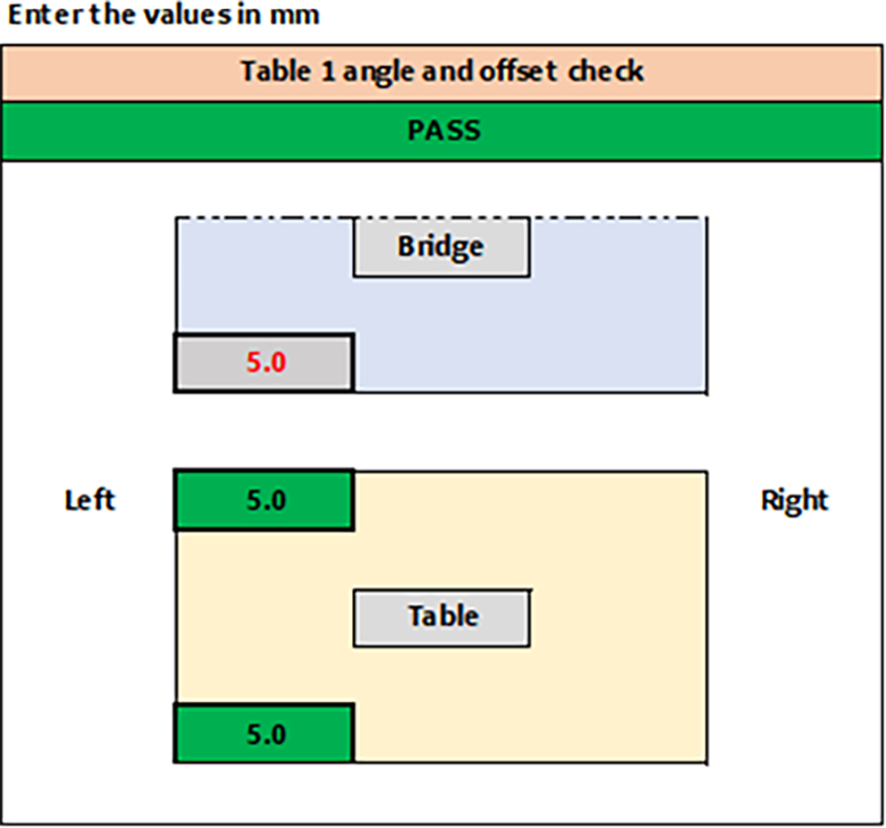
Multi-table configurations
Procedure
Measuring the bridge and rear pedestal heights
About this task
Rear pedestal
Procedure
- Use the vertical rulers to measure the height of the horizontal laser line above the rear leveling feet on the rear pedestal.Note: Do not lean on the rear pedestal while measuring as it could affect the measurement. The vertical rulers can be turned at an angle to view if required.
Figure 9. Vertical rulers on the rear pedestal 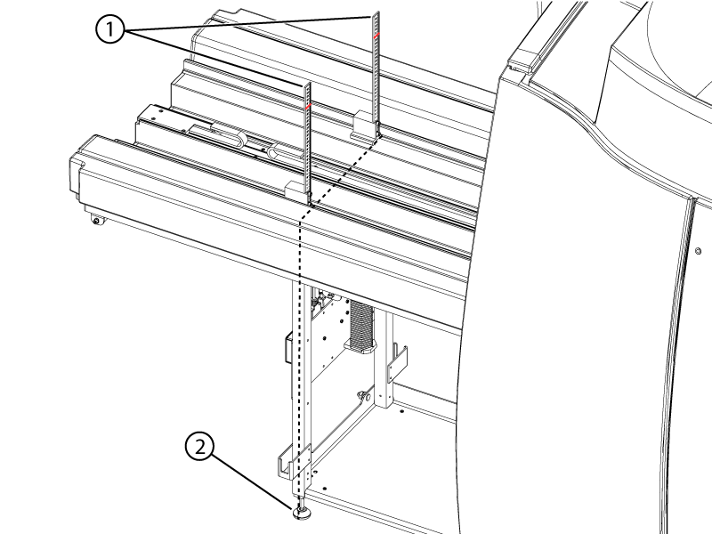
1 Vertical ruler location above rear leveling feet 2 Rear leveling feet - Record the height of the horizontal laser line on each vertical ruler in centimeters.
Figure 10. Sample rear pedestal values in the macro tool 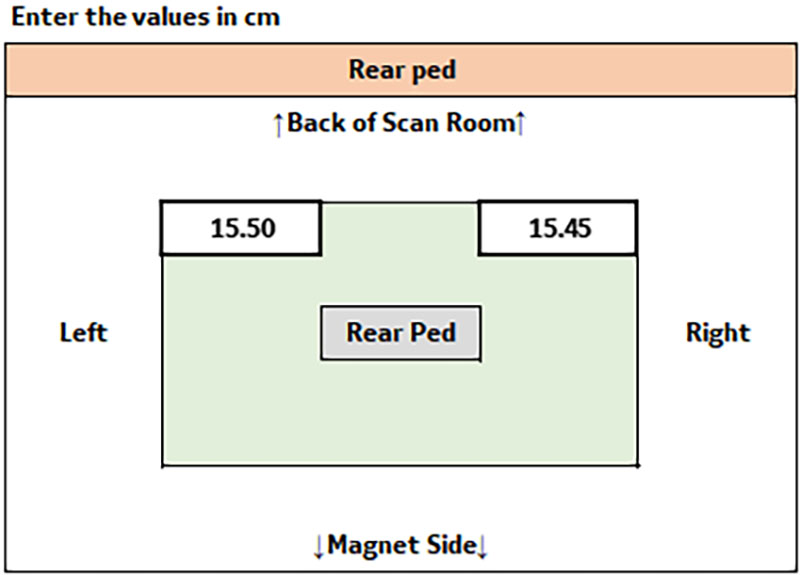
Bridge
Procedure
- Use the vertical rulers to measure the height of the horizontal laser line at the bridge side of the bridge-rear pedestal joint. Record the height of the horizontal laser line on each vertical ruler in centimeters.
Figure 11. Vertical rulers at the rear of the bridge 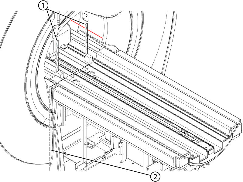
1 Vertical ruler location on bridge at bridge to rear pedestal joint 2 Bridge to rear pedestal joint - Place vertical rulers at the front of the bridge approximately 6 cm into the bore, measured from the end of bridge. Make sure the rulers do not rest on the chamfered surfaces.
Figure 12. Vertical rulers at the front of the bridge 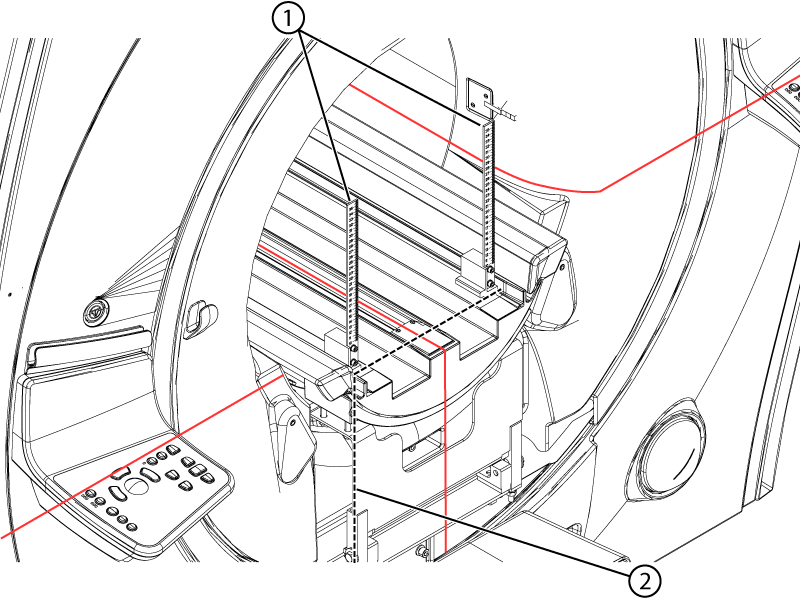
1 Vertical ruler location at front of bridge 2 Front of bridge - Record the height of the horizontal laser line on each vertical ruler in centimeters.
Figure 13. Sample bridge values in the macro tool 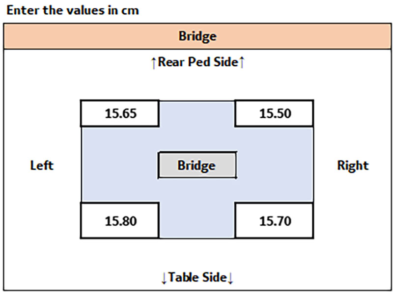
Bridge height in the body coil
Procedure
- Use the brass height tool (5346292) to check the bridge height in the body coil at the front and the rear of the bore.Note: The vertical laser line can be used for laterally centering the brass height tool in the body coil.Note: Make sure the bottom of the brass height tool rests on the bridge and not the belt.
Figure 14. Bridge height in the body coil 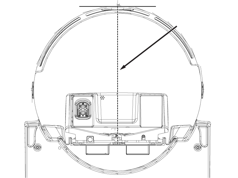
Figure 15. Brass height tool aligned with vertical laser 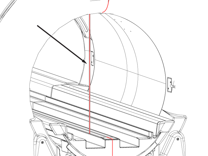
- Record the values in millimeters as they will be entered in the macro tool.Note: The specification for this measurement is 502-505 mm for the narrow bore and 582-585 mm for the wide bore.
Figure 16. Sample bridge height in body coil values in macro tool 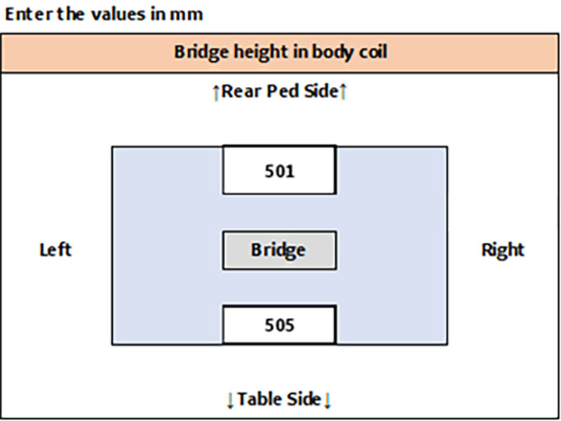
Entering the initial bridge and rear pedestal data in the macro tool
Procedure
Checking the patient table height
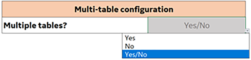
Multiple table configuration
Procedure
Boss 1 height
Procedure
- Remove the front table covers and use the boss height gauge to check the height difference between the table and dock bosses. Make sure to slide the boss height gauge in from the side and that the gauge covers both bosses.Note: A missing front table cover, as shown in the illustration, may result in 16-channel systems reporting a 32-channel connector is not attached. When the adjustment is complete, replace the front cover to prevent this error.Note: The specification for the height difference between the table and dock bosses is less 1 mm. If the boss height gauge does not slide over both bosses from the side, the bosses are outside of the specification.
Figure 18. Boss height alignment check 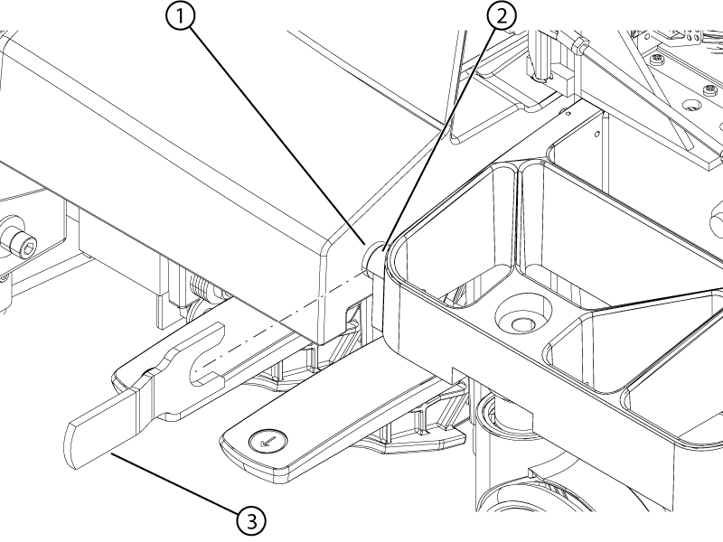
1 Dock boss 2 Table boss 3 Boss height gauge - If the boss height alignment is within specifications, select Pass from the drop-down menu in the macro tool. If the alignment is outside of specifications, select Fail from the drop-down in the macro tool.
Figure 19. Boss height alignment pass/fail drop-down 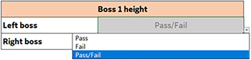
Table 1 check
Procedure
- Record the final table values in the macro tool in centimeters. The tolerance is ± 2 mm of the output values.
Figure 20. Sample table 1 check values in macro tool 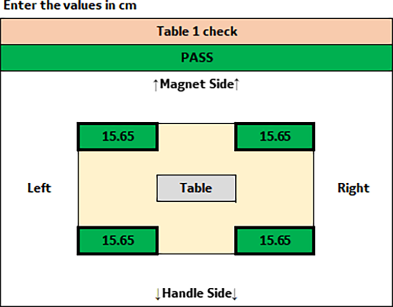
Casters 1 check
Procedure
- At each of the four caster wheel assemblies, measure the height from the floor to the bottom edge of the aluminum support casting.
Figure 21. Caster measurement 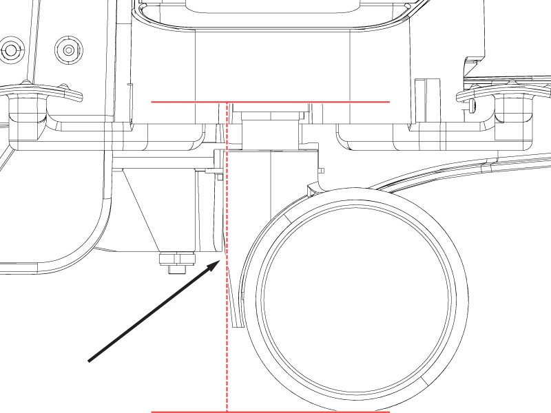
- Record the values for each caster in the macro tool in millimeters. The tolerance is 207 ± 10 mm.Note: If the table casters are not within specifications (207 ± 10 mm), lower or raise the casters until they are at the minimum or maximum depending on the situation.
Figure 22. Sample caster 1 check values in macro tool 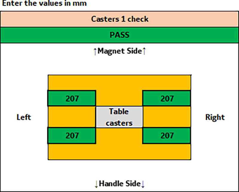
Multiple table configurations
Procedure
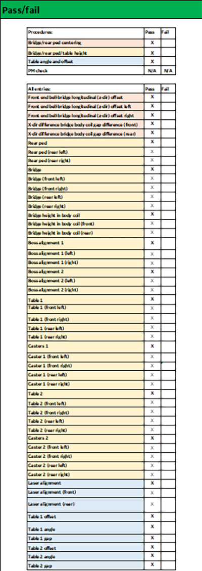
Doing the pass/fail check
Procedure
Uploading data
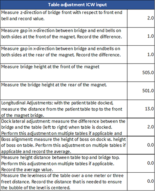
Table adjustment ICW input
Procedure
Save/upload data
Procedure
- Select the Save Session button in the macro tool to save the results from the alignment.Note: Selecting the Save Session button will export a .csv record of the values from the service procedure executed into the same directory of the excel workbook. This is the file that will be uploaded.
Figure 25. Save session 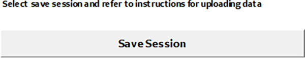
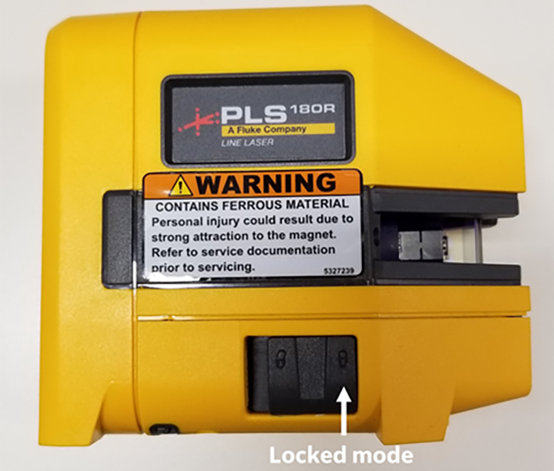
- When the patient handling alignment is complete, place the laser level in locked mode before shipping.
Figure 26. Laser level in locked mode