
- Discovery MR750w and SIGNA™ Architect T 3.0T System Service Methods
- 5690002-2EN Revision 4
- 00000018WIA3021AA50GYZ
- id_20268391.1
- Jun 22, 2020 9:54:26 AM
Setting up and calibrating UPM - MNS
Sets up and calibrates Universal Power Monitor (UPM) and Multi-Nuclear Spectroscopy (MNS) components.
Prerequisites
| Personnel requirements | |||
|---|---|---|---|
| Required persons | Preliminary requirements | Procedure | Finalization |
| 1 | - | 30 minutes | 5 minutes |
| Tools and test equipment | |||
|---|---|---|---|
| Item | Quantity | Part number | Manufacturer |
| RF Power Measurement Kit | 1 |
Either 5307511-2 or 5307511-3 (Bird wattmeter) | - |
| Digital Multimeter | 1 |
| - |
| 3.0T 31P TR Switch (available on site with customer) | 1 |
2354050 (non-RoHS) 5409918 (RoHS) | - |
| ||||
About this task
The AMT amplifier has cable connections at the rear of the cabinet. The CPC amplifier has cable connections at the top of the cabinet.
If you are replacing a UPM board only (rather than performing a full MNS setup), start with Setting up software tool to calibrate UPM - MNS forward power .
Disable VSWR fault detection in AMT amplifier
About this task
This procedure is for the AMT amplifier only. For the CPC amplifier, proceed to Amplifier forward power calibration .
Procedure
- Remove the top panel from the MNS amplifier cabinet.
Figure 1. Top panel of AMT MNS amplifier cabinet 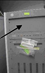
- Remove the top cover of the controller module in the MNS amplifier cabinet.
Figure 2. Top cover of controller module 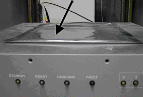
- Locate the SMA cable connections to J7 and J8 on the controller module PCB. Remove the connections and move the cables away from the PCB. Restrain the cables with tape, if necessary.
Figure 3. J7 and J8 on controller module PCB 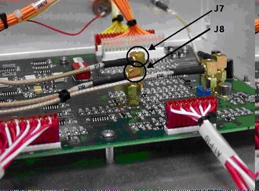
Amplifier forward power calibration
Procedure
-
Inhibit TR faults by moving
SW2
on the driver module in PEN cabinet to the
TR Disable
position.
Figure 4. Driver module switches 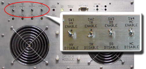
-
Set
RF Enable S2
on the MNS exciter to Disable (down).
Figure 5. MNS exciter RF enable S2 switch location in disable (down) 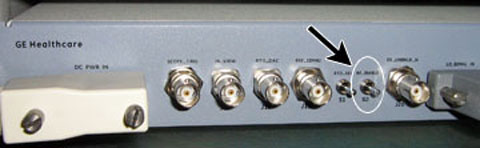
- Remove the transmission cable from RF OUT.
- (For AMT amplifier) Remove cable from J4 .
- (For For the original CPC amplifier, part number 5411744) Remove cable from J3 .
- (For For the new CPC amplifier, part number 5750811) Remove cable from J2 .
Connect directly to the 35 kW 3.0T RF dummy load. Plug the power supply into the dummy load and the power supply into the 100 VAC service outlet in the cabinet.
Figure 6. Setup for MNS output measurement 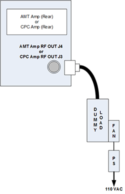
Figure 7. Coupler attached to original CPC amplifier (J3) 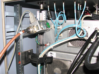
Figure 8. Coupler attached to J2 on power amplifier 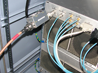
Setting up software tool to calibrate UPM - MNS forward power
About this task
This procedure applies to both the AMT and CPC amplifiers.
Procedure
- Attach the MNS 31P TR switch cabling to the LPCA A connector.
Figure 9. MNS 31P TR switch connection to LPCA (MR750 system shown) 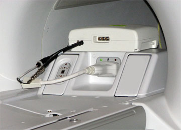
- Start the UPM tool:
- (For non-proprietary Service Tools) From the Common Service Desktop, select Calibration > UPM Tool > Click here to start this tool .
The UPM tool window appears.Figure 10. UPM tool 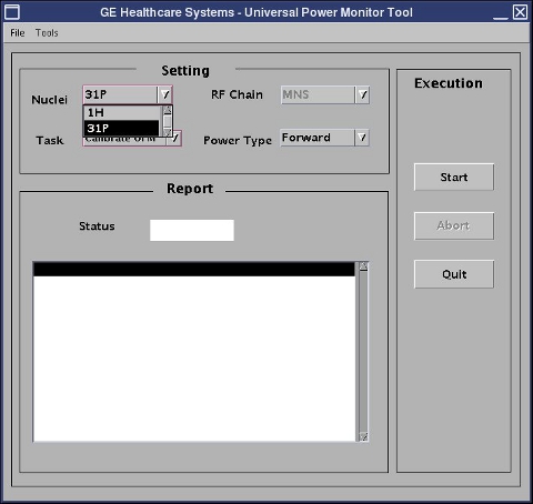
MNS reflected power calibration
Procedure
UPM failure
Procedure
- Ensure proper setup of the calibration equipment.
- Check the cabling between the UPM and the amplifier.
- Check mgd_stage file: cd /w/config . Remove the “ p ” if necessary (p=UPM emulated).
- (For AMT amplifier) Refer to Re-enable VSWR fault detection in AMT amplifier ONLY and perform steps to safely reconnect J7 and J8 cables to the controller module PCB.
- Do the maximum RF power calibration procedure. Repeat the UPM calibration.
- Check the UPM for power.
- Check the error log for details of the UPM failure.
- Do body UPM calibration. If it fails, check the error log.
- If detector boards are replaced, do the UPM calibration to put the new boards into service.
Re-enable VSWR fault detection in AMT amplifier ONLY
Procedure
- Apply LOTO on the RF amplifier and PEN cabinet to remove power to the MNS amplifier. See the MR Service Safety Manual , PN 5452735.
- Remove the top panel of the MNS amplifier cabinet (see Figure 1 ).
- Reconnect the SMA cable connections to J7 and J8 on the controller module PCB (see Figure 3 ).
- Replace the top cover of the controller module in the MNS amplifier cabinet (see Figure 2 ).
- Replace the top panel of the MNS amplifier cabinet.
- Remove LOTO (see the MR Service Safety Manual , PN 5452735) and reapply power to the MNS amplifier.
Finalization
Procedure
- If you have not run the UPM MNS functional check during this procedure, run UPM - MNS Functional Check .
- In the UPM Tool, select Quit .
- Set RF Enable S2 to disable (down) on the exciter Figure 5 .
- Remove the cables and power measurement equipment from the MNS amplifier.
- Reattach the RF OUT cable at the rear of the cabinet.
- Set SW2 to TR Enable (up) on the driver module.
- Set RF Enable S2 to Enable (up) on the exciter.