
- SIGNA MR355 / SIGNA MR360
- Service Manual
- 5856356-3EN Revision 5.0
- Basic Service Documentation. Copyright General Electric Company.
- 00000018WIA308ACF20GYZ
- id_131069891.10
- Jul 5, 2019 11:49:11 PM
Universal Power Monitor - Body Setup and Calibration
Prerequisites
| Required persons | Preliminary requirements | Procedure | Finalization |
|---|---|---|---|
| 1 | Not Applicable | 30 minutes | Not Applicable |
| Item | Quantity | Effectivity | Part number | Manufacturer |
|---|---|---|---|---|
| 25 KW 30 dB Attenuator (Dummy Load) | 1 | - |
46317724p14 | - |
| 50 Ohm Terminator | 1 | - |
46-265874p1 | - |
| 7/16Male -N Female Adapter (Attached in System Cabinet) | 1 | - |
5166139 | - |
| ||||
About this task
This procedure sets up the Universal Power Monitors (UPM’s) in Body Mode, by using the system and the Power Measurement Kit (Wattmeter). For proper calibration of the Universal Power Monitors, (UPM) Forward Power must be completed in Body mode.
BODY FORWARD POWER CALIBRATION
Procedure
- Inhibit TR faults. Disable the Driver Module in the System Cabinet, Figure 1. Move switch 2 to the TR Disable position.
Figure 1. Driver Module Switches 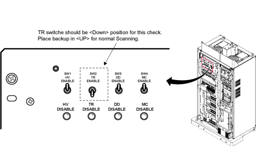
- Remove the Body RF cable from J4. Connect the RF dummy load
into J4. Use 7/16 Male - N Female Adapter attached in System Cabinet.Note:
If the body section of the 1.5T SRFD3 Max Power RF Output and Calibration procedure was just completed, configuration is the same. You can leave the head RF cable disconnected and body can keep the wattmeter in line. It will not change the outcome of the calibration.
Note:7/16Male -N Female Adapter is located at System Cabinet Left Shelf. Remove left cover and find it. See Figure 2Figure 2. Built In Service Tool 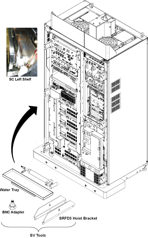
Figure 3. Plug the Dummy Load into J4, Body Out 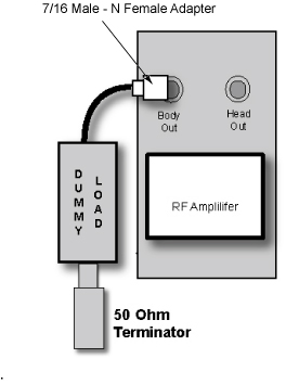
Setting up Software Tool to Calibrate UPM - Body Forward Power
About this task
This tool must see a Landmark only. It is not necessary to have a Head coil in place, or any other scan parameter entered than what is described below. Simply Landmark on the cradle where the Head coil would be.
Procedure
If Head UPM is NOT calibrated before Body UPM Calibration, reset “/w/config/UPM1Cal.cfg” and “/w/config/UPM2Cal.cfg” file to 0 according to the following procedure.Notice - Open File Editor by selecting Utility/File Editor from Common Service Desktop.
Figure 4. File Editor 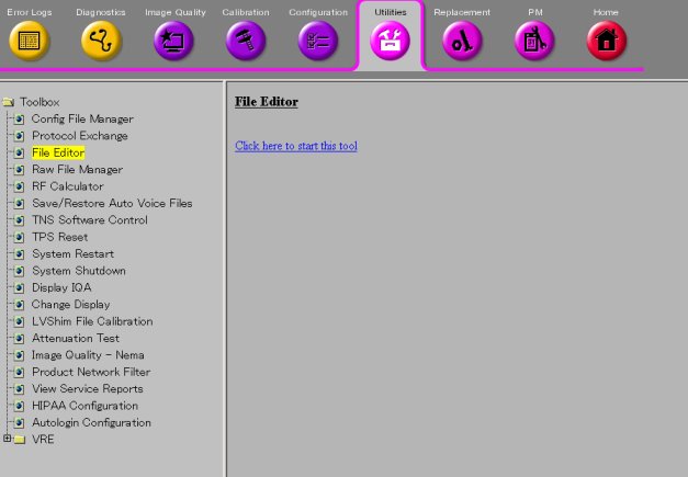
- Select File/Open.
Figure 5. File/Open 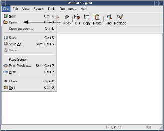
- Select '/w/config/Upm1Cal.cfg' and Open.
Figure 6. Select file 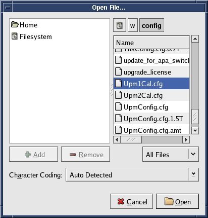
- Select Save As... and save the file as 'Upm1Cal.cfg.bk' .Note:
The purpose of this step is creating backup file.
Figure 7. Save As 
- Select File/Open.
Figure 8. File/Open - Select '/w/config/Upm1Cal.cfg' and Open.
Figure 9. Select file - Edit the file so that the 12 values are set to '0'.
Figure 10. Edit 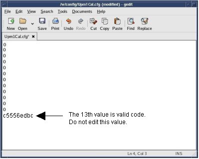
- Save the config file.
Figure 11. Save 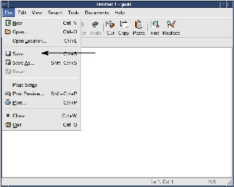
- Open File Editor by selecting Utility/File Editor from Common Service Desktop.
- From the Common Service Desktop Select:
- Start UPM tool from the Service Browser, Figure 12. Figure 13 shows an example of the UPM tool.
Figure 12. Starting UPM Tool 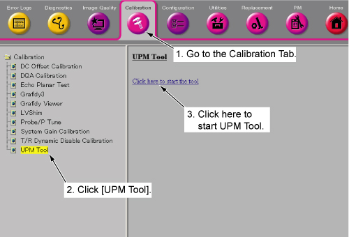
Figure 13. UPM GUI 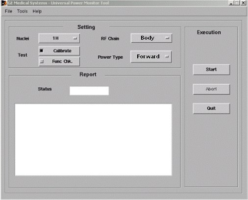 Note:
Note:The first time running the UPM Calibration tool after a load from cold, the following Error may appear: “The spectroRFampType and upm.config do not match! Please run the UPM Tool config file editor and hit [Restore Defaults] and save the config file”. If this error appears, click [File] -> “Edit Config”. When the window opens, click [Restore Defaults] then close the screen. The tool will now have the correct information and this pop-up will not appear again during future UPM Calibrations.
- Start UPM tool from the Service Browser, Figure 12. Figure 13 shows an example of the UPM tool.
Finalization
Procedure
- Place the RF ENABLE switch on front of exciter in the DISABLE (Down) position.
- Remove the cables and power measurement equipment.
- Re-enable T/R Drive. See Driver Module, Figure 1.
- Switch RF ENable on the front of the exciter to the Enable (up) position.
- Upon completion of UPM calibration, Reset TPS. The system will not scan until this step is done