- SIGNA MR355 / SIGNA MR360
- Service Manual
- 5856356-3EN Revision 5.0
- Basic Service Documentation. Copyright General Electric Company.
- 00000018WIA30E35F20GYZ
- id_131069981.2
- Jul 6, 2019 12:17:31 AM
STIF Board SRI PAC Fiber Optic Checks
Prerequisites
| Required persons | Preliminary requirements | Procedure | Finalization |
|---|---|---|---|
| 1 | - | - | - |
| Item | Quantity | Effectivity | Part number | Manufacturer |
|---|---|---|---|---|
| Fiber Optic Light Meter Kit | 1 | - |
46-317830G1 | - |
| ||||||||
| Condition | Reference | Effectivity |
|---|---|---|
| - | - |
About this task
This procedure describes how to turn on the fiber optic drivers in a Signa system. Software output control is provided for the HFBR-1522 drivers (plastic cable) and the HFBR-1414 drivers (glass cable) on the STIF Board in the CAM-Lite Chassis, the HFBR-1522s (plastic cable) on the PAC and the SRI, and the HFBR-1522 drivers (plastic cable) on the MDS peripherals.
STIF BOARD, SRI, PAC FIBER OPTIC CHECKS
Procedure
- The Fiber Optic Test can be selected from the Diagnostics menu.
The drivers on the STIF card (See Figure 1)
remain on until the Fiber Optic Test is canceled. The drivers on the
link remain on until the test is canceled, or a break occurs in the
link upstream from the device being tested.
Figure 1. STIF CARD LOCATION 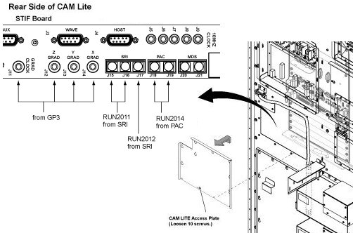
Fiber Optic Power Level Measurement
Procedure
- To turn on the HFBR-1522 drivers on the STIF Board and the HFBR-1522
drivers on the FRI fiber optics and STIF-SRI fiber optics, go to the
Service Desktop on the host computer and start the Service Browser
if it’s not already running by clicking the Service
Browser button on the diagnostics menu on the left side
of the screen. See Figure 2.
Figure 2. STARTING FIBER OPTIC TESTS 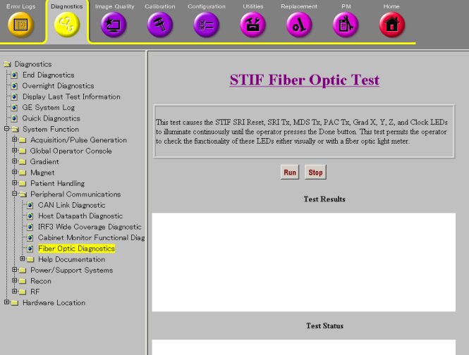
- Remove protective cover and install the appropriate adapter
(46-320033G1 for plastic cables;
FOA-32 for glass cables) onto the fiber optic meter. Plug test cable
(1/2 m for plastic (46-307564P4),
1 m for glass (46-307584P3)) onto
the adapter. See Figure 3.
Figure 3. FIBER OPTIC MEASUREMENT CONFIGURATION 
- Measure transmitter output through test cable with EXFO fiber
optic meter. Compare this value with specification. See Figure 4 .
If value is out of spec, there is a problem. It could be a power supply
problem, transmitter problem, or functional problem with board. Do
not proceed until this value is within spec.
Figure 4. 1.5T FIBER OPTIC POWER LEVELS 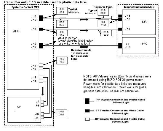 Note:
Note:The fiber optic connectors are a latching type connector. For the plastic cable connectors, press on the latch to release. For the glass cable connectors, press on the outer connector shell and rotate a quarter turn.
TEST SPECIFICATIONS
About this task
The following data characterize fiber optic power levels in a Signa system. Typical data were obtained from a limited sample of systems. Typical values may cover a wide range due to the effects of cable routing, connecting, and cable length which may vary from system to system. Minimum values, however, are absolute, and will be the same for fixed sites, mobiles, and T/R(s).
Procedure
STIF J16 to SRI J11; STIF J17 to SRI J13; SRI J12 to STIF J15;
-
Nonmodulated HFBR-1522 transmitter output through 1/2 m test cable:
Typical: -8.5 dBm
Minimum: -11.2 dBm
-
Nonmodulated HFBR-1522 transmitter output through 147 ft cable:
Typical: -21.5 dBm
Minimum: -23.0 dBm
Gradient (glass) Data Links: (AMP fiber 502083-1 with ST type connectors and 820 nm HFBR-1414/HFBR-2416 transmitter/receiver pair)
STIF J14 to GP J2; STIF J13 to GP J3; STIF J12 to GP J4; STIF J11 to GP J1:
-
Nonmodulated HFBR-1414 transmitter output through 1 m test cable:
Typical: -15 dBm
Minimum: -18.0 dBm
-
Nonmodulated HFBR-2416 transmitter output through 46 ft glass cable:
Typical: -16 dBm
Minimum: -20.0 dBm
Do not observe the light directory. Use white paper and reflect the beam to observe.
STIF J18 to PAC J9; STIF J19 to PAC J10;
Finalization
Procedure
- Turn off the fiber optic meter. Disconnect all kit components
used in measurement scheme and return to kit. See Figure 5.
Figure 5. Fiber Fiber Optic Light Meter Kit