
- SIGNA MR355 / SIGNA MR360
- Service Manual
- 5856356-3EN Revision 5.0
- Basic Service Documentation. Copyright General Electric Company.
- 00000018WIA300D8E20GYZ
- id_131072453.0
- Aug 29, 2019 1:42:18 AM
Head, Body, or Head and Body System Gain Calibration
Prerequisites
| Required persons | Preliminary requirements | Procedure | Finalization |
|---|---|---|---|
| 1 | Not Applicable | 30 minutes | 10 minutes |
| Item | Quantity | Effectivity | Part number | Manufacturer |
|---|---|---|---|---|
| Foam Wedges or Pads | As required | - | - | - |
| Nesting Plate (if required) | 1 | 1.5T or 3.0T | - | - |
| NiCl TLT Head Sphere | 1 | 1.5T |
46-265826G6 | - |
| Head Loader | 1 | 1.5T |
46-287899G1 | - |
| Body TLT Sphere | 1 | 1.5T |
46-265635G6 | - |
| SPT Body Loader | 1 | 1.5T |
2135652-2 | - |
| Head SNR Sphere | 1 | 3.0T |
2359877 | - |
| Head Loader | 1 | 3.0T |
2360031 | - |
| Head Loader Positioner | 1 | 1.5T and 3.0T |
5110241 | - |
| 3T Body Sphere | 1 | 3.0T |
2360025 | - |
| SPT Loader | 1 | 3.0T |
2360037 | - |
| DQA Phantom with Loader (if required) | 1 | 1.5T |
2321556 | - |
| DQA Phantom with Loader (if required) | 1 | 3.0T |
2371512 | - |
| ||||||||
| Condition | Reference | Effectivity |
|---|---|---|
|
Signa software is fully operational. | - | - |
|
No image artifacts are present. | - | - |
| - | - |
Procedure
- Note:If using the Split-Top Head Coil, place the Head Coil into the clinical position on the table and plug it in.
This procedure is for Head, Body and both Head and Body System Gain calibration.
-
Follow the instructions in the first step if using a Split-Top Head Coil.
-
Proceed to Step 2 if using a Quad Head Coil.
- Place the Head SNR Sphere with the loader on the Head Coil Positioner
into the Head Coil as shown.
Figure 1. SNR Sphere on Head Loader Positioner in Head Coil 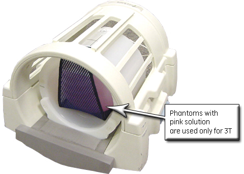 Note:
Note:Phantoms contain read green solution for 1.5T systems, and pink solution for 3.0T systems.
- Turn on the alignment lights, and LANDMARK on the black centerline line of the Head Loader shown below.
Figure 2. Landmarking on Centerline of Head SNR Sphere 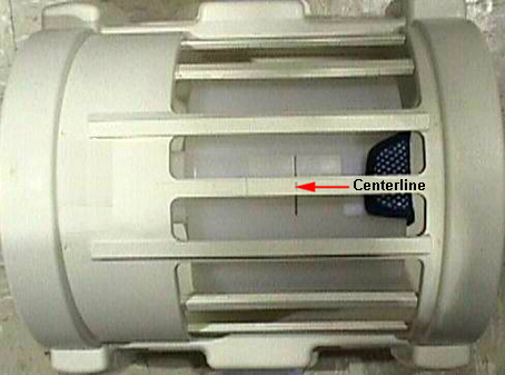
-
- If using a nesting plate:
- Push the nesting plate against the front of the head coil to
eliminate any gap.
Figure 3. Nesting Plate Setup 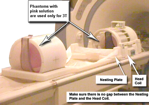
- Push the nesting plate against the front of the head coil to
eliminate any gap.
- If not using the nesting plate:
- With landmark still set on the Head Loader, drive the table
in until the position reads 1135 mm.
Figure 4. Distance Between Head Coil Landmark and Centerline on Body Loader 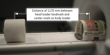
- With landmark still set on the Head Loader, drive the table
in until the position reads 1135 mm.
- Start the System Gain Calibration tool.
To start non-proprietary service tools:
-
From the Common Service Desktop, select the Calibration icon.
-
Select System Gain Calibration from the calibration menu, then select Click here to start this tool.
Figure 5. Starting System Gain Calibration 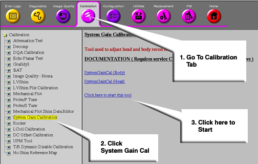 Note:
Note:If running System Gain after initial software load, the system will prompt for the proper nesting plate. Type 1 for the short nesting plate or 2 for the long nesting plate. If the nesting plate type is incorrect, manually delete the nesting plate file and run System Gain again. The nesting plate file is located at: /w/config/spt_nesting.
-
- Wait for the calibration to complete with the results.
-
If no adjustment is required and the calibration was successful, the screen shown below displays.
-
If adjustments are required, Do you want to save the recon scale factor displays. Type y.
Figure 6. Calibration Output 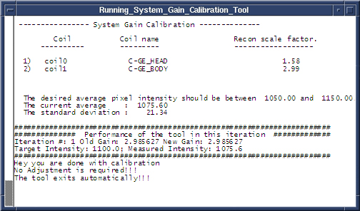
-
Finalization
- Perform separate check scans using coils for which System Gain (i.e. Head or Body or both) has just been run to ensure proper system operation.
- Remove all phantom(s), loader(s), positioner, head coil, pads and nesting plate (if used) from the bore and table.