
- SIGNA MR355 / SIGNA MR360
- Service Manual
- 5856356-3EN Revision 5.0
- Basic Service Documentation. Copyright General Electric Company.
- 00000018WIA30250030GYZ
- id_131065753.0
- Aug 29, 2019 1:54:20 AM
Flex Coil MCQA procedure
Prerequisites
| Required persons | Preliminary requirements | Procedure | Finalization |
|---|---|---|---|
| 1 | 0 minutes | 30 minutes | 0 minutes |
| Item | Quantity | Effectivity | Part number | Manufacturer |
|---|---|---|---|---|
| Head TLT Sphere | 1 | - |
46-265826G6 | - |
| Head Loader | 1 | - |
46-287899G1 | - |
| Condition | Reference | Effectivity |
|---|---|---|
|
The following coil configuration names must be installed to run this tool: Check the system coil configuration for 1.5T 4Ch Large Flex Coil and 1.5T 4Ch Small Flex Coil configuration. If 1.5T 4Ch Large Flex Coil and 1.5T 4Ch Small Flex Coil have not been installed, select 1.5T 4Ch Large Flex Coil and 1.5T 4Ch Small Flex Coil from the list of available coils, and install. | - | - |
About this task
Follow this process to prepare for the SNR test using the 1.5T 4Ch Flex coil suite.
| GE Part number | Description |
| 5430693 | 1.5T 4Ch Large Flex Coil |
| 5430694 | 1.5T 4Ch Small Flex Coil |
Large Flex Coil
Procedure
- The Quad Head Coil must be completely removed from the cradle before performing any body or surface coil scans. Failure to do this may result in damage to the Quad Head Coil T/R network.
- Set the phantom and 1.5T 4Ch Large Flex coil on the cradle as
following steps.
- Put the coil on velcro tape and align center of the coil and
center of the cradle.Note:
Place the 1.5T 4Ch Large Flex coil far enough from LPCA so that the coil cable won't be placed under the coil to avoid the low SNR.
Figure 1. Setup 1 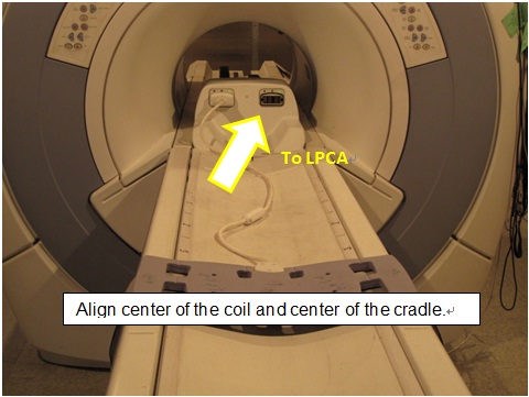
- Place the phantom with holder on S-I center of the 1.5T 4Ch
Large Flex Coil.
Figure 2. Setup 2 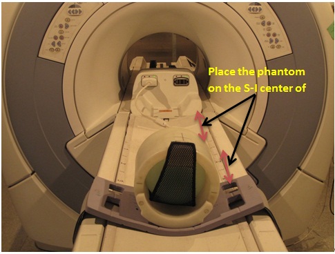
- Wind the 1.5T 4Ch Large Flex Coil around the phantom holder
and fix by the Velcro tape on the strap.
Figure 3. Setup 3 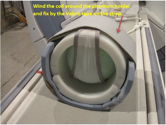
- Verify that the coil cable is not placed under the coil.
Figure 4. Setup 4 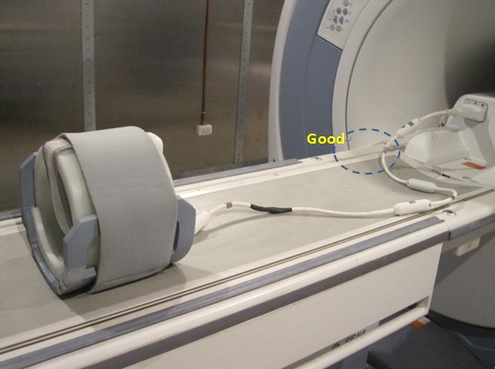
- At the magnet, press “Alignment Light” button to
turn on the light. Move the cradle to align the coil to the alignment
lights. Press “Landmark” button to landmark the alignment.
Figure 5. Setup 5 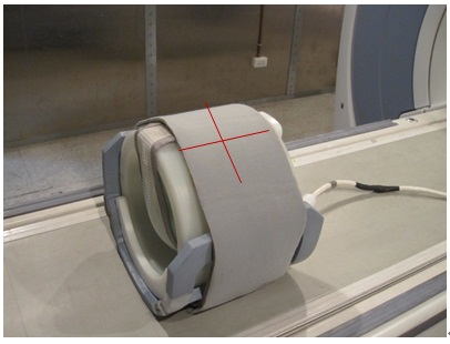
- Put the coil on velcro tape and align center of the coil and
center of the cradle.
- Move the coil to scan position by pushing the “Move to Scan” button, ensuring cable does not get snagged.
- Perform MCQA Tool. Refer to Multi-Coil Quality Assurance Tool .
Small Flex Coil
Procedure
- The Quad Head Coil must be completely removed from the cradle before performing any body or surface coil scans. Failure to do this may result in damage to the Quad Head Coil T/R network.
- Set the phantom and 1.5T 4Ch Small Flex coil on the cradle as
following steps.
- Align center of the coil and center of the cradle.Note:
Place the 1.5T 4Ch Small Flex coil far enough from LPCA so that the coil cable won't be placed under the coil to avoid the low SNR.
Figure 6. Setup 1 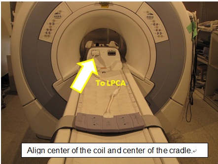
- Place the phantom with holder on S-I center of the 1.5T 4Ch
Small Flex Coil.
Figure 7. Setup 2 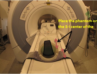
- Wind the 1.5T 4Ch Small Flex Coil around the phantom holder
and fix by the Velcro tape on the strap.
Figure 8. Setup 3 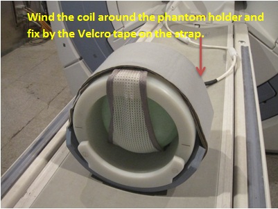
- Verify that the coil cable is not placed under the coil.
Figure 9. Setup 4 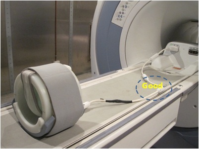
- At the magnet, press “Alignment Light” button to
turn on the light. Move the cradle to align the coil to the alignment
lights. Press “Landmark” button to landmark the alignment.
Figure 10. Setup 5 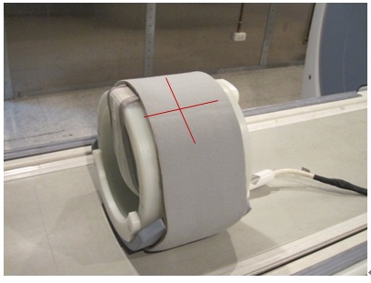
- Align center of the coil and center of the cradle.
- Move the coil to scan position by pushing the “Move to Scan” button, ensuring cable does not get snagged.
- Perform MCQA Tool. Refer to Multi-Coil Quality Assurance Tool .
Finalization
Finalization
No finalization steps.