Basic Service Documentation. Copyright General Electric Company.
Object ID: 00000018WIA3062EF20GYZ
Topic ID: id_13106038 Version: 3.0
Date: Aug 29, 2019 1:55:22 AM
Express Coil: Head Neck Array Coil ID PCB Replacement
Prerequisites
Table 1. Personnel requirements
Required persons
Preliminary requirements
Procedure
Finalization
1
0 minutes
30 minutes
0 minutes
Table 2. Tools and test equipment
Item
Quantity
Effectivity
Part number
Manufacturer
Standard tool kit
– Flathead screwdriver, 10 in-lbs torque driver, 15in-lbs torque driver,
Spanner and pliers
1
-
-
-
Table 3. Safety
Notice
Observe Anti-Static Precautions.
About this task
Follow this process to change the Coil ID PCBs for Express Coil-
Head Neck Array.
Procedure
Notice
Wear the static electricity prevention wrist band when accessing the cables below cradle not to damage the electronics module.
Unscrew the bottom cover and remove from coil. Retain
the original screws used.
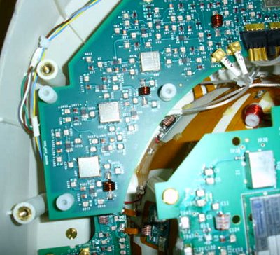
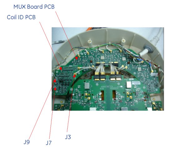
Identify the Coil ID PCB located on Mux Board. See Figure 1 Identify and Remove DC Connectors Pins (J7 & J9) and one DC PCX Connector (J3) on Coil ID PCB.
Figure 1. Mux Board and Coil ID PCB Locations
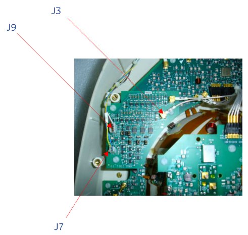
Unscrew the 3 screws of Coil ID PCB as shown in Figure 2 and carefully
remove the Coil ID assembly. Retain the removed 3 screws carefully.
Figure 2. Mux Board and Coil ID PCB Locations
Note:
Ensure that only two DC Connectors (J7, and J9) and one
DC PCX Connector (J3) are removed from System Cable.
Mount the new coil ID PCB assembly with 3 screws in the open
slot on the Mux Board. See Figure 3.
Figure 3. Coil ID PCB Locations
Connect the J7 and J9 DC Connector of System Cable Assy to Coil ID PCB at J7 and J9 as shown in Figure 2. Connect the J3 DC PCX Connector to J3 DC PCX connectors on Coil ID PCB. Verify that all labels on the connectors match those on the Mux Board and Coil ID Board.
Replace cover. Use original screws to fasten cover.

 Note:
Note: