Basic Service Documentation. Copyright General Electric Company.
Object ID: 00000018WIA3032EF20GYZ
Topic ID: id_13107230 Version: 3.0
Date: Aug 29, 2019 1:55:21 AM
Express Coil: Head Neck Array Coil Cable Replacement
Prerequisites
Table 1. Personnel requirements
Required persons
Preliminary requirements
Procedure
Finalization
1
0 minutes
40 minutes
0 minutes
Table 2. Tools and test equipment
Item
Quantity
Effectivity
Part number
Manufacturer
Standard tool kit
– Flathead screwdriver, 10 in-lbs torque driver, 15in-lbs torque driver,
Spanner and pliers
1
-
-
-
Table 3. Replacement parts
Item
Quantity
Effectivity
Part number
Manufacturer
Head Neck Array
Cable Assy
1
-
5365878
-
Table 4. Safety
Notice
Observe Anti-Static Precautions.
About this task
Follow this process to change the system cable for coils that
have a cable available as a spare part.
Procedure
Notice
Wear the static electricity prevention wrist band when accessing the cables below cradle not to damage the electronics module.
Unscrew the bottom cover and remove from coil. Retain
the original screws used.
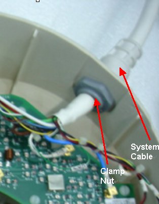
Unscrew the cable clamp nut from the coil as shown in Figure 1. Retain the original nut used.
Note:
When re-installing components, the nut must be attached
back
Figure 1. Removing the Cable Clamp
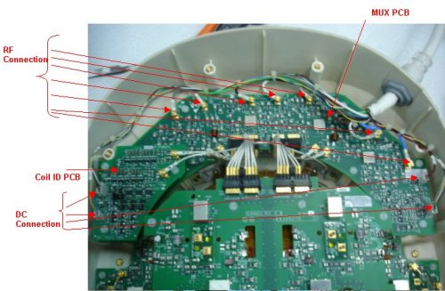
Identify the Mux Board Assembly and the Coil ID PCB located
on the Mux Board (Head Neck Unit (HNU) Only). See Figure 2.
Figure 2. Mux Board and Coil ID PCB Locations
Identify all the RF (CH1-CH8) Connectors and DC Connectors Pins
(J3, J5 and J10on Mux Board and J7, J9 on Coil ID Board). See Figure 2.
Remove all RF connectors (CH1-CH8) from Mux Board. See Figure 2. Pliers may
be necessary for removal of the RF (PCX) connectors, as they may be
difficult to unplug. This will help prevent accidental breakage of
the cables.
Remove DC connectors (DC) J3, J5 from MUX Board and J7, J9 from
Coil ID PCB. See Figure 2.
Remove GND connectors –J10 from Mux board assy.
Remove the system cable (without the coil id).
Install the new system cable.
Align the cable into the notch of former slot. Screw down cable
clamp nut using the spanner
Connect RF connectors (CH1-CH8) to Mux Board (CH1-CH8). Verify
that all labels on the connectors match those on the Mux Board. See Figure 2.
Connect DC connectors (J3 & J5) to Mux Boards and J7 and
J9 to coil ID PCB. Verify that all labels on the connectors match
those on the Mux Board and Coil ID Board. See Illustration 2.
Connect GND connectors J10 to the Mux Board. Verify that all
labels on the connectors match those on the Interface Board. See Figure 2.
Replace cover. Use original screws to fasten cover.