Basic Service Documentation. Copyright General Electric Company.
Object ID: 00000018WIA30C8FD20GYZ
Topic ID: id_13107047 Version: 3.0
Date: Aug 29, 2019 1:52:19 AM
1.5T HNS NCU Connector Bracket Replacement
Prerequisites
Table 1. Personnel requirements
Required persons
Preliminary requirements
Procedure
Finalization
1
15 minutes
1 hours
15 minutes
Table 2. Tools and test equipment
Item
Quantity
Effectivity
Part number
Manufacturer
6 in. long 1/4 in.
Slotted Screwdriver (Suggested: Screw Holder/Screw Starter)
1
-
-
-
1/8 in. Slotted
Screwdriver
1
-
-
-
Wrist Strap and
Grounding Cord
1
-
-
-
Table 3. Replacement parts
Item
Quantity
Effectivity
Part number
Manufacturer
FRU Kit 1.5T
HNS NCU Conn Brkt
1
-
5352453
-
Table 4. Safety
Notice
Follow all standard Personal Protection Equipment requirements.
About this task
This procedure applies to Revision 3, 1.5T Head, Neck, Spine
(HNS) Coils only (refer to rating plate for revision number). It
details the replacement of the NCU connector bracket on the posterior
portion of the HNU.
Procedure
Notice
A properly grounded wrist strap must be worn by the Field Engineer (FE) performing this procedure.
Run the HNS Coil MCQA Tool for the Posterior Head-Face and Posterior
Head-Chest Horseshoe TL configurations to verify the coil is functioning
properly prior to rework. Refer to 1.5T HNS Coil MCQA Setup to set up the coil.
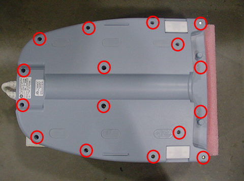
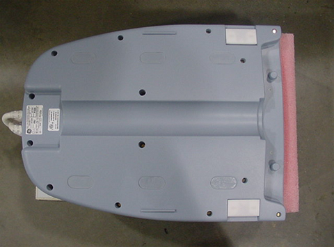
Remove the bottom cover of Head-Neck unit. Set bottom cover
and the brass screws aside.
Figure 1. Removing Bottom Cover
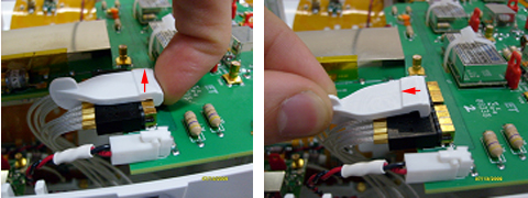
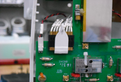
Unplug NCU Connector RF and DC Cables from the CH11 Feedboard.
Gently pull up on the RF Connector Retainer, then remove it
by pulling back on the small vertical tab. Set the retainer aside.
Figure 2. Removing RF Connector Retainer
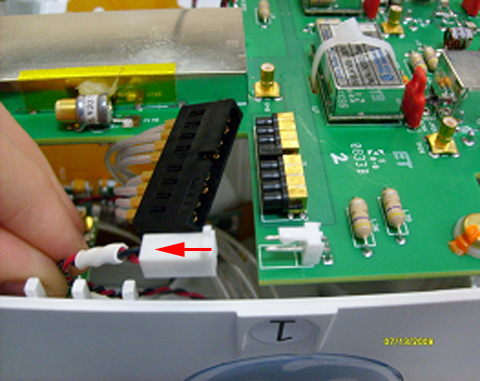
Unplug the DC Connector by pulling on the white connector housing.
Figure 3. Unplugging DC Connector
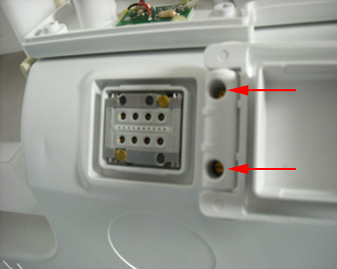
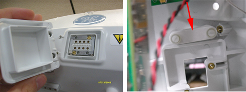
Using a 1/8 in. slotted screwdriver, remove the two external
screws from the NCU Cover, and set them aside.
Figure 4. Removing Cover Screws
Remove the NCU Connector cover and inner threaded retainer.
Set these items aside.
Figure 5. Removing NCU Connector Cover and Retainer
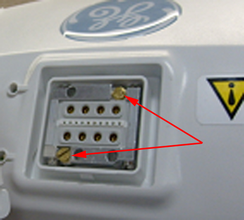
Remove the two brass screws from the NCU Connector, and set
them aside.
Figure 6. Removing Brass Screws
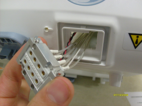
Remove the NCU Connector by carefully pulling the cables through
the posterior former wall, and set the connector aside.
Figure 7. Removing NCU Connector
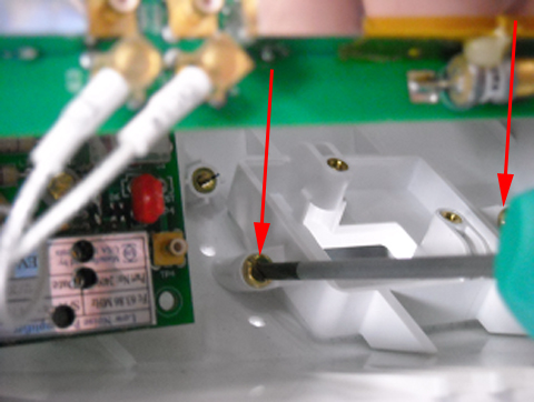
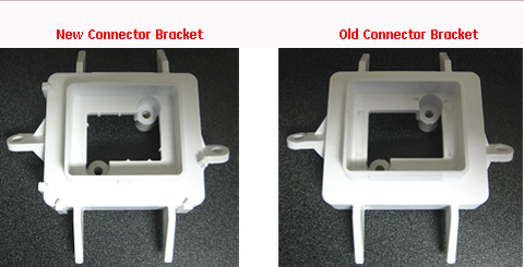
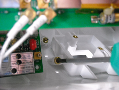
Using a 6 in. long slotted screwdriver, remove the two mounting
screws from the NCU Bracket. Discard the old bracket and the brass
mounting screws.
Install the new bracket with the brass screws included in FRU
Kit using the 6 in. long slotted screwdriver.
Figure 10. Installing New Bracket
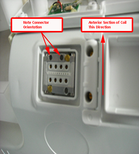
Reinsert the NCU Connector into the housing, and install using
the two brass screws removed earlier. Tighten the screws until the
connector is fully seated, then tighten an additional one-eighth turn.
Figure 11. Reinserting NCU Connector
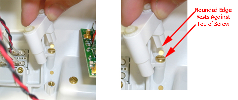
Reinstall the inner threaded retainer, making sure to orient
it correctly.
Figure 12. Reinstalling Retainer
While holding the inner threaded retainer, reattach the NCU
cover. Tighten the screws until the cover is fully seated, then tighten
an additional one-eighth turn.
Figure 13. Reattaching NCU Cover
Reattach the RF and DC cables to the CH11 Feedboard.
Figure 14. Reattaching Cables
Reinstall the lower cover of the HNS unit using the brass screws
removed earlier.
Figure 15. Reinstalling HNS Cover
Finalization
Verify the coil functionality by running the HNS Coil MCQA Tool
for the Posterior Head-Face and Posterior Head-Chest Horseshoe TL
Configurations. Refer to 1.5T Head Neck Spine (HNS) Coil MCQA Setup to set up the coil.