
- SIGNA MR355 / SIGNA MR360
- Service Manual
- 5856356-3EN Revision 5.0
- Basic Service Documentation. Copyright General Electric Company.
- 00000018WIA30D8FD20GYZ
- id_131070464.0
- Mar 23, 2020 2:45:17 PM
1.5T Head Neck Spine (HNS) Coil MCQA Setup
Personnel Requirements
| Required Persons | Procedure |
| 1 | 45 mins |
Overview
Follow this process to prepare for the MCQA test.
The coil consists of five units: Posterior Head, Face, Chest, Horseshoe, and TL. This is done to ensure modularity in design and diagnostics. The MCQA test for the coil is conducted to three configurations: TL unit only, Posterior Head Chest Horseshoe TL, and Posterior Head Face.
Coils do not ship with phantoms. Phantoms come in a unified phantom set with the MR system.
Preliminary Requirements
Tools and Test Equipment
| Item | Quantity | Part # | Manufacturer |
| TL Unified Phantom | 2 | 5343347 | Dielectric |
| Large Cylindrical Unifed Phantom | 1 | 5342679 | Dielectric |
| Phantom Positioner HNS | 1 | 5344844 | Medical Comfort |
Safety
No special safety requirement.
Required Conditions
The appropriate coil configuration file must be installed to run this tool. See “Section 4 - Coil Config” of the HNS Coil Installation Procedure document: 3282174.pdf.
Procedure
Coil Serial Numbers
Record the coil serial numbers for the Posterior Head, Chest, and Thorasic Lower (TL) components.
|
Posterior Head Component
|
Serial # __________________ |
|
Chest Component
|
Serial # __________________ |
|
Thorasic Lower Component
|
Serial # __________________ |
Legacy Phantom Setup
If installing the coil for the first time in a system, please refer to Auto Coil Install.
1.5T phantoms are green.
-
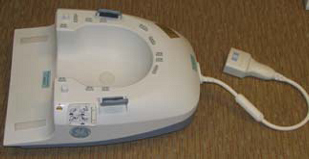
To position the coil in the cradle, connect the cable as shown in Figure 1:
Figure 1. Connecting the Coil 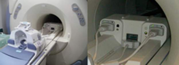
-
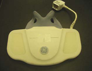
Remove the pads and place a phantom in the coil as shown in Figure 2.
Figure 2. Positioning Phantom for the TL Unit, Posterior Head Chest Horseshoe TL and Posterior Head Face Configurations of the HNS Coil 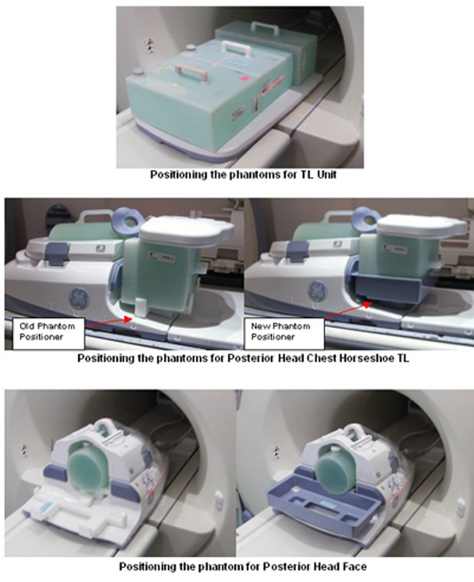 Note:
Note:The MCQA tool can ONLY run on one individual mode connected at a time. The MCQA tool will not run with a combination of modes and will report that the configuration is invalid.
-
Landmark at the positions shown in Figure 3, Figure 4, and Figure 5, as the case may be.
Figure 3. TL Only Setup Landmarking 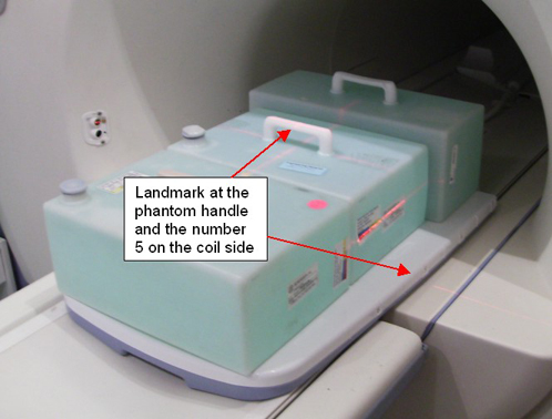
Figure 4. Posterior Head Chest Horseshoe TL Setup Landmarking 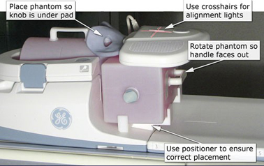
Figure 5. Posterior Head Face Setup Landmarking 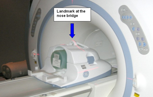
-
Perform the Multi-Coil Quality Assurance Tool test.
HNS Unified Phantom MCQA Setup
Mode 1: Posterior Head Face Section
-
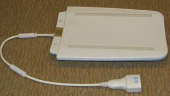
Place Posterior Head Face section on the table as shown in Figure 6.
Figure 6. Positioning the Posterior Head Face Section 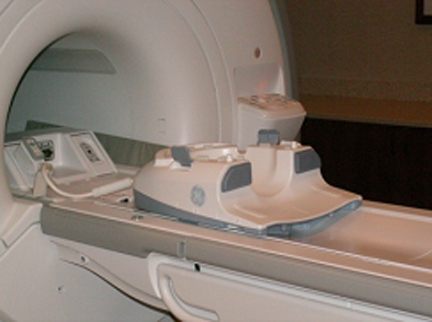
-
Place HNS positioner and then place large cylindrical unified phantom on the positioner as shown in Figure 7.
Figure 7. Positioner and Large Cylindrical Unified Phantom 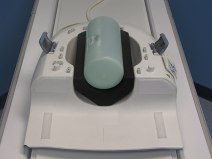
-
Carefully align the face component part of the coil with the connector pins over this posterior head face section and latch both the coil sections into place as shown in Figure 8. (The scanner will not operate if the coil sections are not latched correctly.)
Figure 8. Aligning Coil with Connector Pins 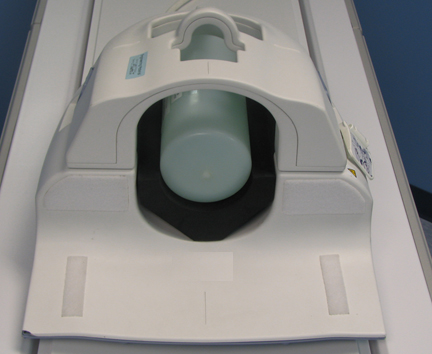
-
Connect the coil to the system LPCA.
-
Landmark the coil on the markings present on the face component indicated through arrows as shown in Figure 9 and press advance to scan.
Figure 9. Landmarking the Coil 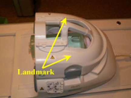
-
Perform the Multi-Coil Quality Assurance Tool test.
Mode 2: Posterior Head Chest, Horseshoe and TL Section
-
Place the Posterior Head Face section, horseshoe adapter, and TL section of the coil on table as shown in Figure 10.
Figure 10. Positioning the Coil Components 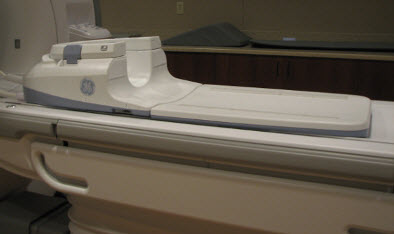
-
Place the HNS phantom Positioner, large cylindrical unified phantom, and TL unified phantom as shown in Figure 11. The TL unified phantom shall be positioned over the junction of the TL section and head components.
Figure 11. Complete Setup 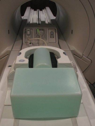
-
Ensure that TL unified phantom is in contact with the cylindrical unified phantom as shown in Figure 12.
Figure 12. TL Unified Phantom in Contact with Cylindrical Unified Phantom 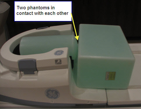
-
Connect the chest part to the posterior head section as shown in Figure 13.
Figure 13. Connecting Chest Part to Positioner Head 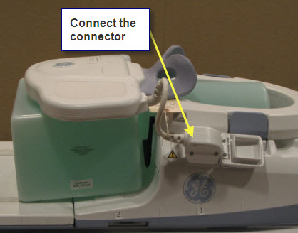
-
Landmark on the markings over the chest section of the coil as indicated in Figure 14.
Figure 14. Landmarking Coil 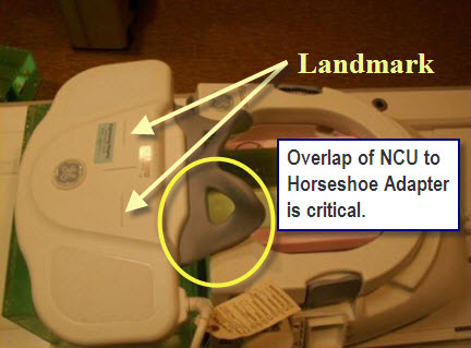
-
Press advance to scan.
-
Perform the Multi-Coil Quality Assurance Tool test.
Mode 3: TL Section
-
Place the TL section of the HNS coil on the table as shown in Figure 15.
Figure 15. Positioning TL Section 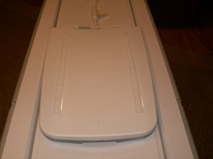
-
Place TL unified phantoms on the TL section of the coil as shown in Figure 16.
Figure 16. Positioning Phantom on Coil 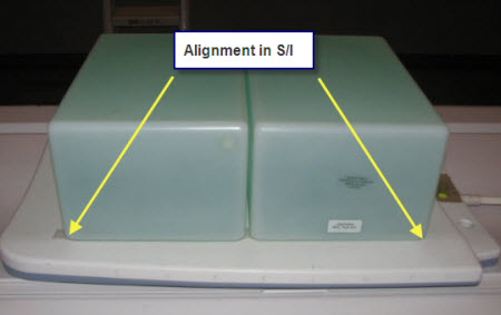
-
Align the TL unified phantoms properly in S/I direction and R/L direction of the TL section of the coil as shown in Figure 17.
Figure 17. Aligning the Unified Phantoms 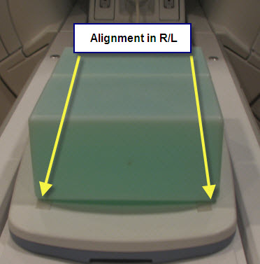
-
Connect the coil to Port A of system LPCA.
-
Landmark on #5 present on the side of the TL section of the coil as shown in Figure 18 and press advance to scan.
Figure 18. Landmarking Coil 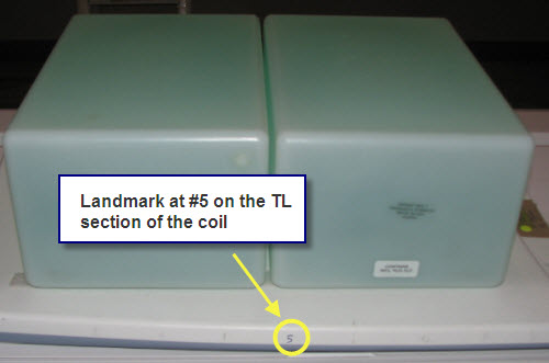
-
Perform the Multi-Coil Quality Assurance Tool test.