
- SIGNA MR355 / SIGNA MR360
- Service Manual
- 5856356-3EN Revision 5.0
- Basic Service Documentation. Copyright General Electric Company.
- 00000018WIA30AB0F20GYZ
- id_131069634.0
- Mar 23, 2020 2:47:59 PM
1.5T Cardiac Coil Setup for MCQA Test
Prerequisites
| Required persons | Preliminary requirements | Procedure | Finalization |
|---|---|---|---|
| 1 | Not Applicable | 15 minutes | Not Applicable |
| Item | Quantity | Effectivity | Part number | Manufacturer |
|---|---|---|---|---|
| Legacy Phantom Kit | 1 | Legacy Phantom Set |
2304255-3 | - |
| TL Unified Phantom Set | 1 | Unified Phantom Set |
5343347 | - |
| Condition | Reference | Effectivity |
|---|---|---|
|
For HDx, HDxt and HDe, the following coil configuration names must be installed to run this tool: HDx CardiacServ. | - | - |
|
For Discovery MR450 and Optima MR450w, the following coil configuration names must be installed to run this tool: GE_HDx 8Cardiac. | - | - |
About this task
This procedure prepares for the automated SNR test using the 1.5T HDx Cardiac Array by GE/USAI, catalog M3335MD.
Note:
Coils do not ship with phantoms. Phantoms come in a unified phantom set with the MR system.
Legacy Phantom Setup
Procedure
- Note:Place the Posterior Coil on the table as shown, using the long patient pad between the table end and the posterior coil.
If installing the coil for the first time in the system, refer to Auto Coil Installation.
Figure 1. Placement of Posterior Coil 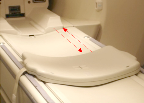
- Place the Phantom onto the posterior coil, then guide the phantom
into position by lining up the locator pins on the phantom with the
locator holes in coil as shown below.
Figure 2. Phantom Positioned on Posterior Coil 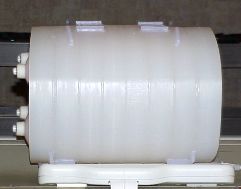
- Place the Anterior Coil on top of the phantom, and use the patient
straps to secure in place as shown.
Figure 3. Anterior Coil Positioned on Phantom 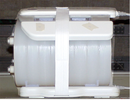
- Landmark by aligning the laser light with the coil crosshairs
as shown below.
Figure 4. Landmarking with Crosshairs on Anterior Coil 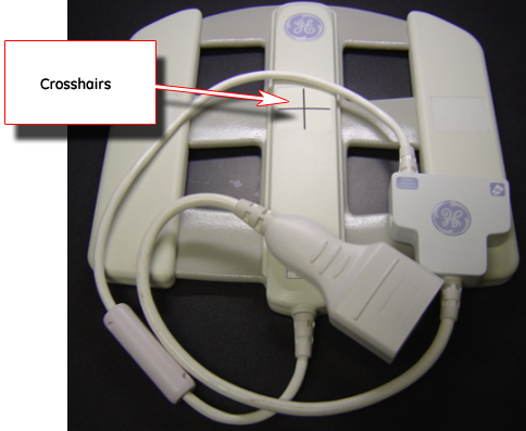
Unified Phantom Setup
Procedure
- Place the posterior section of the coil on the table as shown.
Figure 5. Posterior Section of Coil on Table 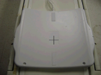
- Place the TL Unified Phantoms over the posterior section so
the phantom set is well centered in the S/I and R/L directions as
shown in both illustrations below.
Figure 6. Phantom Set Centered in S/I Direction 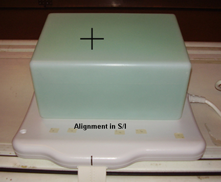
Figure 7. Phantom Set Centered in R/L Direction 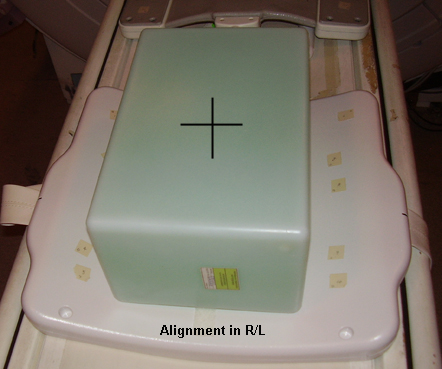
- Place the anterior section onto the phantom set so the coil
is well centered in both S/I and R/L directions as shown.
Figure 8. Coil Centered in Both S/I and R/L Directions 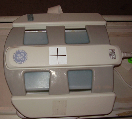
- Fasten the Velcro® straps to firmly snug the coil to the
phantom as shown below.
Figure 9. Placement of Velcro Straps 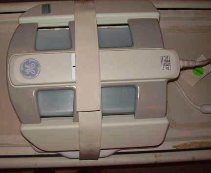
- Landmark the coil at the crosshairs as shown below, and Advance to Scan.
Figure 10. Landmarking on Coil Crosshairs 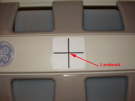
Finalization
Finalization
No finalization steps.