
- SIGNA MR355 / SIGNA MR360
- Service Manual
- 5856356-3EN Revision 5.0
- Basic Service Documentation. Copyright General Electric Company.
- 00000018WIA30982F20GYZ
- id_131068303.0
- Aug 29, 2019 1:55:03 AM
Express Coil: Anterior Array Coil Troubleshooting
| Required persons | Preliminary requirements | Procedure | Finalization |
|---|---|---|---|
| 1 | 0 minutes | 30 minutes | 0 minutes |
| Item | Quantity | Effectivity | Part number | Manufacturer |
|---|---|---|---|---|
| Digital Multi-meter | 1 | - |
N/A | - |
| TL UNIFIED PHANTOM | 2 | - |
5343347 | - |
| Item | Quantity | Effectivity | Part number | Manufacturer |
|---|---|---|---|---|
| Some tests may require FRUs for diagnosis. | - | - | - | - |
| Condition | Reference | Effectivity |
|---|---|---|
|
The following coil configurations must be installed to run the MCQA test for the coil: Express Body12 Express Body23 Express Body34 | - | - |
The following tips can be used to troubleshoot common problems with the Express Anterior Array Coil.
Receiving No Signal
-
Problem: You are unable to pre-scan or are scanning and yet receiving no signal.
-
Possible Solution: Refer to the following steps.
- Verify the green lights above the port A is illuminated. This indicates the coil is properly plugged into the system.
- Verify that the system has correctly detected the coil by checking
in the “Currently Connected” in the GUI to select coils
in Rx as shown in the example in Illustration 1.
Figure 1. Currently Connected Coils Window In The Scan Screen 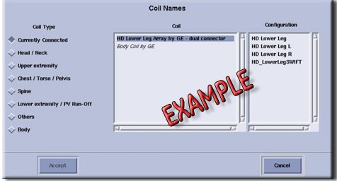
- Verify that the scan locations and any FOV offsets are correct.
- Perform a continuity check on the output cable (Section 4.4). The continuity check must be performed by a GE authorized Service Engineer.
- Verify that the coil is positioned with the cable exiting towards the bore.
- Verify that the cable is not looped or crossed.
There can also be a problem at the system interface port. If you still cannot get a signal, try to scan (transmit and receive) with the body coil. For this test, be sure to remove the imaging coil from the magnet bore before you scan with the body coil. If you still receive no signal the problem probably lies with the MR system. If the scan completes successfully, there is probably a problem with the coil. Contact GE for further assistance. If you are unable to scan with the substitute coil, there may be a system problem related to this particular coil type.
Image Quality
-
Problem: Poor IQ, shaded images, or if MCQA fails
-
Possible Solution: Refer to the following steps.
- Perform a continuity check on the output cable. The continuity check must be performed by a GE authorized Service Engineer.
- Verify that there are no loops in the cables.
- Verify that there are no metal or ferromagnetic objects close to the coil, patient or magnet (i.e., safety pin, hair pin).
- Verify that the coil is properly positioned.
- Verify that your center frequency is within the frequency adjustment range for your system.
- Verify that the R1, R2 and TG values from the pre-scan are within
normally expected ranges.
If you have not done so already, perform the coil Quality Assurance test (refer to Operator’s Manual ). If the values you obtain do not fall within normal operating parameters, investigate this further by performing a phantom scan with the body coil. For this test, be sure to remove the imaging coil from the magnet bore before you scan with the body coil. If you still have the same problems, there is probably an MR system problem. If the body coil scan is satisfactory, acquire a scan using another coil of the same type (receive-only, phased array) and . If the image quality is visibly improved, there may be a problem with the coil. Contact GE for further assistance.
Artifacts
-
Problem: There is a black line or signal void on the image.
-
Possible Solution: Verify that there is no metal present in the area being scanned in or on the patient.
Output Cable Check
Visual check
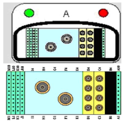
- Before removing the cable assembly from the coil, visually inspect all coaxial connectors and pins on the coil connector. Figure 2 shows the pin layouts of the coil connector. The connector of the 1.5T Anterior Array Coil UNO-E has 2 DC pins in column A, 2 DC Pins Column J and 6 DC pins in column M, 4 RF coaxial connectors columns C. If there are any broken, deformed or recessed pins or coaxial connectors, replace the cable assembly.
- Visually inspect to ensure the availability of 4 RF coaxial Connectors and 10 DC Pin are available in Cable Receptacle Connector.
- If there is any damage to any of the RF Center Pins or DC Pins. Remove the cable assembly from the coil. See Express Coil: Anterior Array Cable Replacement.
- If there is no damage to Cable assy proceed to Anterior Array System Cable Assy Check.
Anterior Array System Cable Assy Check
The Anterior Array coil has Port A Receptacle that is connected to Port A of MR System.
- Note:
The center pins of the System Connector receive coaxial connectors are extremely fragile. Do not attempt to make any measurements at these center pins.
Note:Check if any pin in Table 6 (Center Pin of Cable Side Coax RF Connectors) is shorted to the ground. The outside conductor of a coaxial connector in column C can be used as ground. If any pin is shorted to ground, perform Express Coil: Anterior Array Cable Replacement.The following procedure will rule out a short to GND for each of the signal pins detailed in the following table and ensure the integrity of the ground connection for each RF coax cable. This check does not determine continuity for each of the RF signal connections. With the coil cable disconnected, use a Multimeter to assure no open circuit condition exists between the RF ground shields of the RF coax connector in the system side and the coils side (Refer to Table 1) Use the Multimeter to assure an open circuit condition exists between the center pin and the shield for each RF connector in the coil side.
Table 6. 8Ch “A” connector RF Allocation System Side Coax Center Pin (RF) Coil Side Connector RF Center Pin C1 (CH1) J1 (Clear) C2 (CH2) J2 (Black) C3 (CH3) J3 (Grey) C4 (CH4) J4 (Brown) Figure 3. Coils Side Cable Connectors 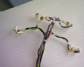
- If one or more of the readings indicate a short, replace the cable. If all of the above readings indicate an open circuit condition, proceed to the DC Lines Continuity Check.
- DC Lines Continuity Check
With the coil cable disconnected, use a multimeter to determine continuity between the designated pins for each control line below. Also test the continuity between the pairs of pins within system connector that are listed in the Table 2 below. If any line or pair of pins indicates an open, replace the output cable.
Table 7. “A” connector DC Allocation System Side Connector DC Pin Coil Side Connector DC Center Pin Signal Short between A1 to A2 N/A coil present and return Short J9 to J10 N/A body transmit enable M3 J5-Pin 1(Brown) +10Vdc (preamp power) M3 J6-Pin 1(Green) M3 J7-Pin 1(Gray) M3 J8-Pin 1(White) M6 J5-Pin 2(Violet) Return for +10Vdc preamp power M6 J6-Pin 2(Yellow) M6 J7-Pin 2(Blue) M6 J8-Pin 2(Red) Short between M9 to M10 N/A coil present and return
Finalization
No finalization steps.