
- SIGNA MR355 / SIGNA MR360
- Service Manual
- 5856356-3EN Revision 5.0
- Basic Service Documentation. Copyright General Electric Company.
- 00000018WIA30B72F20GYZ
- id_131060333.0
- Aug 29, 2019 1:55:00 AM
Express Coil: Anterior Array Cable Replacement
Prerequisites
| Required persons | Preliminary requirements | Procedure | Finalization |
|---|---|---|---|
| 1 | 0 minutes | 30 minutes | 0 minutes |
| Item | Quantity | Effectivity | Part number | Manufacturer |
|---|---|---|---|---|
| Standard Tool Set | 1 | - | - | - |
| ||||
Cable Removal
Procedure
- Remove all 10 screws from the cover as shown in the Figure 1.
Figure 1. 10 screws 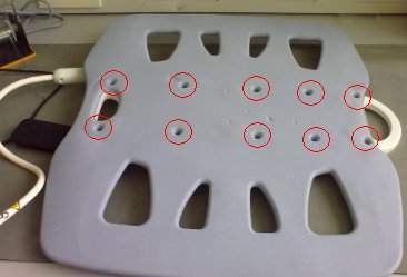
- Unscrew cable clamp. See Figure 2.
Figure 2. Unscrew cable cramp 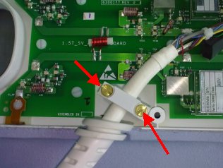
- Locate and disconnect all 4 RF cables and 4 DC cables coming
from the cable assembly. See Figure 3
Figure 3. RF Cable and DC Wire Removal 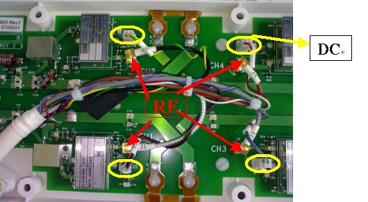
- Remove the cable from the coil. See Figure 4.
Figure 4. Cable Removal 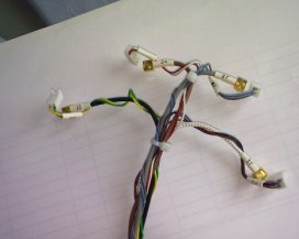
Cable Installation
Procedure
- Place strain relief in cut-out.
Figure 5. strain relief 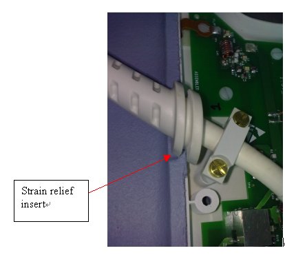
- Secure cable clamp over cable until tight with the previously
removed brass screws.
Figure 6. brass screws 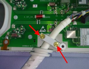
- Attach the RF wires to J1, J2, J3, J4 and DC wires to J5,J6,J7,J8.
Figure 7. RF wires and DC wires 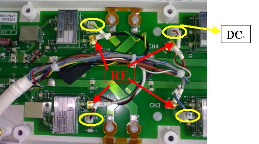
Finalization
Procedure
Perform Express Coil MCQA Test .