
- SIGNA MR355 / SIGNA MR360
- Service Manual
- 5856356-3EN Revision 5.0
- Basic Service Documentation. Copyright General Electric Company.
- 00000018WIA30542F20GYZ
- id_131075783.0
- Aug 29, 2019 1:54:55 AM
1.5 HD 8Ch CTL Coil Troubleshooting Tips
Overview
The following tips can be used to troubleshoot common problems with the HD 8CH CTL Coil by GE-USAI.
Tools and Test Equipment
Digital Voltmeter
Some tests may require Phantoms for IQ Testing.
Required Conditions
The HD 1.5T 8CH CTL coil must be installed in the system.
Procedure
Coil Fault or Coil Connection Fail
Problem:
The system reports a coil fault during prescan or does not recognize the coil connection to the system when selected in the software.
Possible Solutions:
Refer to the following Table.
| Probable Cause | Suggested Actions | Resolution |
| The coil connector has become disconnected from the system interface. | Check to make sure the coil connector is fully engaged. | Engage connector and try the scan again. |
| There is a DC short or open somewhere within the DC path inside the coil. | Perform Section 4.1.1, External Cable Check. | If there is no cable damage detected, replace the coil. |
| The output cable has a short or an open. | Perform Section 4.1.1, External Cable Check, to confirm. | Replace the coil cable assembly. |
| Coil ID issues. | From CSD, select Diagnostics, Manual Tests, SRI Functional Checks, and run the SRI Coil ID test. Compare the coil ID value found to that listed in the coil configuration. | If the value does not match, or no coil ID is found, perform HD 8CH CTL Cable Replacement. |
External Cable Check
Visual check
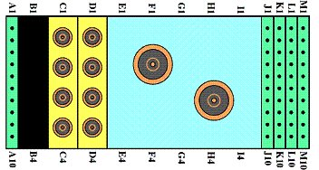
Before removing the cable assembly from the coil, visually inspect all coaxial connectors and pins on the coil connector. Figure 1 shows the pin layouts of the coil connector. The connector of the CTL coil has 2 pins in column A, 8 pins in column J, 7 pins in column M, four coaxial connectors in Column C and four coaxial connectors D, If there are any broken, deformed or recessed pins or coaxial connectors, replace the cable assembly.
Under no circumstances should the continuity of the center pin of the coax connectors be measured. They may be extremely fragile when improper tools are used.

Check for continuity of DC lines in the external cable
Step 1 – Remove the cable assembly from the coil as described in Section 4 of HD 8CH CTL Cable Replacement.
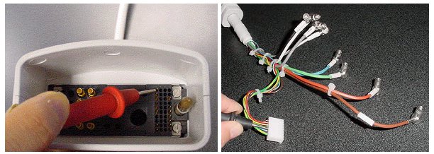
Step 2 – There are six pins in column J (see Figure 1) connecting to DC wires of the cable. Table 2 shows these pins and corresponding DC wires. Use a Digital Volt Meter (DVM) to check the resistance between the pin in column J and the corresponding DC wire (see Figure 3). The resistance should be 5.6 ± 0.5W. If any resistance reading is not within this range, perform HD 8CH CTL Cable Replacement.
| Pin in column J | 1 | 2 | 3 | 4 | 5 | 6 |
| DC wire color | Blue | Purple | Yellow | Green | Brown | Red |
| DC bias of the system | MC1 | MC2 | MC3 | MC4 | MC5 | MC6 |
Step 3 – Check if any pin from J1 to J6 is shorted to the ground. The outside conductor of a coaxial connector in column C or D can be used as ground. If any pin is shorted to ground, perform HD 8CH CTL Cable Replacement.
Check for continuity of the preamp bias
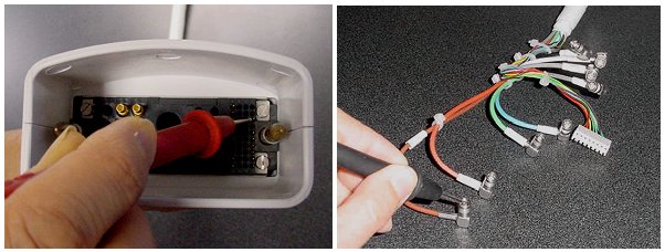
The Pin M3 is connected with eight RF cables. The system supplies the preamp bias voltage through Pin M3 and RF cables to the coil. Referring to Figure 1 and 3, find Pin M3. Use a DVM to check resistance between Pin M3 and the central pin of the SMB connector at the end of each RF cable (see Figure 4). The resistance should be 5.6 ± 0.5W. If any resistance reading is not within this range, perform HD 8CH CTL Cable Replacement.
N/A
N/A
Does not Pass MCQA
Problem:
The coil does not pass MCQA or exhibits poor image quality on patient scans.
Possible Solution:
Refer to the following Table.
| Probable Cause | Suggested Actions | Resolution |
| One or more of the coil channels has a high noise level. | Perform the MCQA test. Review Results. | Replace the coil. |
| One or more of the coil channels has low signal. | Perform the MCQA test. Review Results. | Replace the coil. |