
- SIGNA MR355 / SIGNA MR360
- Service Manual
- 5856356-3EN Revision 5.0
- Basic Service Documentation. Copyright General Electric Company.
- 00000018WIA30A19230GYZ
- id_156668371.9
- Jul 4, 2020 12:40:10 AM
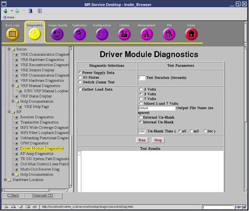
Doing the I/O status diagnostic
This test displays the status of the listed circuits internal to the driver module.
Disclaimer
Depending on your service agreement, not all service tools, diagnostics, and utilities referenced in this document may be accessible. Contact your sales person for information on available service license packages.
Diagnostic description
Diagnostic path
Purpose
- Multi_coil switch (always blue)
- Dynamic drive switch
- T/R switch
- Power status (always blue)
- High speed cable (always blue)
- Front panel interface
- Un-blank cable
- Un-blank harness
- High voltage switch
- Fan 1
- Fan 2
- MCD1 (always blue)
- MCD2 (always blue)
- TR/DD
- Head overtemp
- Body overtemp
- MNS overtemp
- CAN board
- CAN ISO 5 volts
- CAN Flash 5 volts
- DCB reset state
Components tested
Driver module
Test sequence
- Select I/O Status.
- Click Run.
Results
- Test results
-
Diagnostic results display the test/component name with one of the following statuses: PRESENT/NOT PRESENT, FAULTS ENABLED/FAULTS DISABLED. NORMAL/NOT NORMAL, DEFECT/NO DEFECT, or OPERATIONAL/NOT OPERATIONAL. These statuses act like a PASS or FAIL.
Diagnostic results display a status of Pass or Fail. If you receive a Fail status, click GE System Log to view the error message. The system log records errors with the date, time, the process tested, and a detailed error message.
- Test status
-
This window informs you of the progress of the test from the initial scan to the completed diagnostic.