- id_2001446
- Version: 8.1
- Date: Dec 19, 2019 9:18:50 PM
Doing UPM functional check for head channel
Procedure
- On the front of the exciter, set the RF ENB switch to the disabled (down) position.
- Reconnect the system body transmit cables J4 and J22.
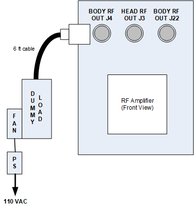
- For head mode, disconnect J3 and connect the dummy load to J3.note:
Use the 7/16 Male to N Female adapter (included in the kit) to make this connection.
Figure 1. Connect dummy load
- Set the RF enable switch to the On position.
- note: Be sure to check the resistance as noted in the Dummy load resistance check and setup procedure, prior to starting the UPM functional check.In the UPM tool, make the following UPM functional check selections:
- Click Start.
- Click Yes when the prompt asks if the hardware setup is correct.
- Review the system prompts as they are displayed during test execution. This functional check takes 2 to 3 minutes before any user interaction is required. Functional check tests include: 10-second average power check, RF inhibit test, and short-term average power fault host trip test.
- From the CSD, open the error log. Make sure the error log contains the message that the UPM has detected a power fault.
- If the error is displayed in the log, the functional test has passed. Click Yes on the dialog box.
- If the functional check passes, click Quit.
- If the test fails, go to UPM troubleshooting.