- id_15667659
- Version: 1.11
- Date: Jul 4, 2019 7:12:13 PM
Doing the coil ID stress diagnostic (DPP)
Depending on your service agreement, not all service tools, diagnostics, and utilities referenced in this document may be accessible. Contact your sales person for information on available service license packages.
Diagnostic path
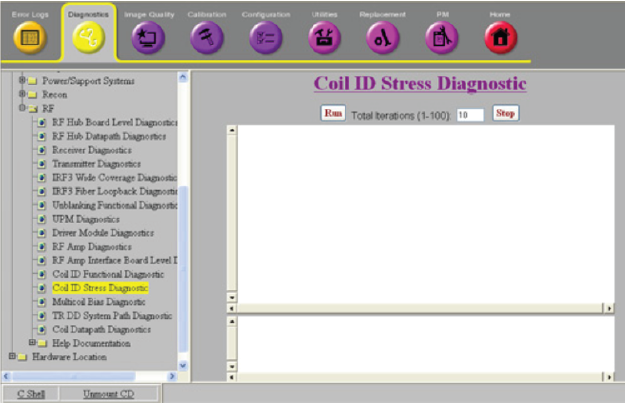
Figure 1. Coil ID stress diagnostic
Purpose
This diagnostic tests the communication path for retrieving and displaying coil ID information. It is intended to be used to troubleshoot intermittent coil detection or ID problems.
Components tested
- RRxPPort
- Cable track 25-pin DC interface
- RxDist
- ICE
- Host
Requirements
One or more coils plugged into the system
Block diagrams
Test sequence
- Navigate to Coil ID Stress Diagnostic.
- To perform something other than the number of test iterations shown, enter a different value in the Total iterations (1-100) field.
- Click Run.
When the Coil ID Stress Diagnostic runs, the following operations are performed:
- The SCP in ICE re-reads all coils connected to the RRxPPorts.
- The SCP checks the coil present pins on the coil port cables (RRxPPort J3, J4).
- For each coil port cable with the coil present pins shorted, the SCP starts a 1-wire read of the coil ID information from the 1-wire coil ID chip(s) in the coil.
- When the 1-wire operations complete, the SCP communicates with the host to get the coil information from the coil database.
- After all the coil connectors with a coil have been read, the sequence is run again until it reaches the number of iterations given.
- After the host responds with the coil information or if the host communication is down, the SCP displays the coil ID information to the diagnostic screen.
Results
To be able to run the stress test, one or more coils must be detected. If no coils are detected, the diagnostic fails.
For each iteration, the stress test prints out the coil information read and error indications. Check the display for any differences in coil information between iterations. If any differences are noted between iterations, this could indicate an intermittent system problem.
notice: when checking or reseating cables, always turn the system power off, otherwise it may cause a system problem.
| Result | Description | GE field action |
|---|---|---|
| ERROR: This diagnostic cannot run due to HW emulation. | Required hardware (IRF, Receiver, and coil ID) are emulated. | Remove emulation from /w/config/mgd_stage, TPS reset, and retry diagnostic. |
| Bootup processing still running. Wait a minute and try again. | TPS reset has failed, but hardware and firmware initialization required by this diagnostic is not complete yet. | Wait a minute for initialization to complete, then retry the diagnostic. |
| ERROR: No DVMR fiber link to the RxDist module found. | The SCP and RxDist are not communicating over the fiber link. | Check subsequent error messages to determine possible cause for communication failure and next action. Possible causes include RxDist input power failure, internal RxDist power regulation failure, RxDist clock cable not attached or clock signal failure, bad RxDist SFP module. This error could also be caused by a bad or disconnected fiber cable between ICE and RxDist. Try running the DVMR Link Status Diagnostic. |
| ERROR: the ICE to RxDist cable is not connected. | The ICE to RxDist 25-pin cable is required to be connected. |
|
| RRxPPort is communicating to the SCP over its fiber link, but RxDist does not detect that the RRxPPort 44-pin cable is connected. | Check RxDist to RRxPPort 44-pin cable and try reseating it. | |
| The RxDist detects a RRxPPort cable connection, but that RRxPPort does not have good digital power. |
|
|
| The RxDist detects a RRxPPort cable connection, but that RRxPPort does not have a good clock signal. |
|
|
| The RxDist detects a RRxPPort cable connection, but that RRxPPort does not have a good SFP module. |
|
|
| The RxDist detects a RRxPPort cable connection, but that RRxPPort does not have DVMR link communication with ICE. |
|
|
| ERROR: RxDist analog power fault. | RxDistribution analog power is bad. | |
| RRxPPort 5V or 3.3V power is bad. | Replace the RRxPPort. | |
| RRxPPort -10V power is bad. | Replace the RRxPPort. note: This error can occur if cables are swapped when running the Coil Datapath Diagnostic. Make sure that the errors were logged during the Coil ID Diagnostic before replacing the RRxPPort.
|
|
| RRxPPort +10V power is bad. | Replace the RRxPPort. note: This error can occur if cables are swapped when running the Coil Datapath Diagnostic. Make sure that the errors were logged during the Coil ID Diagnostic before replacing the RRxPPort.
|
|
| RRxPPort has an intermittent power fault. | Replace the RRxPPort. | |
| ERROR: Not enough receiver fiber links found. | ICE cannot communicate with enough receiver modules for this system configuration. |
|
| ERROR: Not all receivers are in applications mode. | Some receivers’ FPGA(s) are not running the application code yet. |
|
| ERROR: The DVMR links are not ready. | Some DVMR link nodes are not ready. |
|
| ERROR: Internal receiver diags have failed. Check error log for details. | DPP runtime initial checks failed. |
|
| (Error log) An RRX module did not echo a command value sent to it from ICE over its dual fiber cable. | A DVMR link command from ICE to a receiver module failed. | Look for DVMR link errors in the log and troubleshoot the device that caused the link to go down. Try running the DVMR Link Status Diagnostic. |
| Diagnostic aborted due to DVMR fiber link fault. | DVMR link communication failed. | Look for DVMR link errors in the log and troubleshoot the device that caused the link to go down. Try running the DVMR Link Status Diagnostic. |
| Diagnostic aborted due to a failed attempt to read a coil ID from port X. | Could not read coil ID from port X. |
|
| A coil ID error has occurred. | The SCP reports a failure to read the coil ID information over the 1-wire line to the coil ID chip. |
|
| Coil is invalid. | There is a problem with the information in the coil ID chip or coil database. | Check that the coil is installed in the coil database. |
| No coils detected with coils connected. | The RRxPport is not reporting that a coil is connected. This means that the coil present lines are broken between the coil and the RRxPPort. |
|
| Coil ID reads timed out. | Coil ID response from the host was not received. |
|
| The MCRv tool was detected. The MCRv tool is not allowed in this diagnostic. | This diagnostic does not support the MCRv tool connected directly to the RRxPPort. |
|