- id_12373353
- Version: 1.4
- Date: Aug 14, 2019 8:02:18 PM
Set Current
Disclaimer
Depending on your service agreement, not all service tools, diagnostics, and utilities referenced in this document may be accessible. Contact your sales person for information on available service license packages.
Diagnostic Description
Diagnostic Path
Diagnostics > Hardware Location > Pen Panel Cabinet > Shim Supply Diagnostics
Diagnostics > System Function > Magnet > Shim Supply Diagnostics
Purpose
This diagnostic provides operator control for the current on each channel and confirms through read back that the desired current is set.
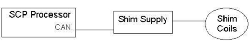
This diagnostic is part of the Shim Supply Diagnostics, comprised of a series of tests that verify and display various shim supply values by communicating from the SCP to the shim supply via the CAN link.
Components Tested
-
Shim supply
-
Coil channels
-
RTD channels
Requirements
Software configuration:
-
Standard software
-
CAN communications NOT emulated
Hardware configuration:
-
CAM chassis: SCP and AGP processor boards and bridge board
-
Shim supply, cabling, etc.
Block Diagram
Figure 1. SHIM Supply Block Diagram
Test Sequence
-
Enter a current for each of the channels 1-6. (–4.000 ≤ current ≤ 4.000).
note:The shim power supply can supply a maximum of 12 amps. If you attempt to set current to more than 12 amps on all six channels, the test will fail and the remaining channels will show 0 (zero) amps and test errors will be logged. This is an expected output. To test the maximum current on all six channels, test each channel individually.
-
Select Set Current Test, then click Run.
-
The diagnostic issues a command that sends the non-zero current values to the shim supply.
-
The diagnostic waits, allowing the command to set the channels’ current.
-
The diagnostic issues a command that instructs the shim supply to return the present voltage and current for each coil channel.
-
The diagnostic displays the results.
The shim supply automatically checks to ensure it is in the proper state before running the test. Commands to the shim supply are issued via the CAN interface on the SCP.
Expected Results
A typical test output is shown in the illustration below. On the actual display, input errors, shim supply state errors, and test condition errors are indicated in red.
Figure 2. Sample Output of Shim Supply Diagnostic Results
Finalization
Before scanning, perform a TPS reset.