- Topic ID: id_23554483
- Version: 3.0
- Date: Dec 22, 2021 11:22:34 PM
Tube Replacement - RT16
Prerequisites
Overview
This procedure applies to following RT CT Systems.
-
LightSpeed RT16 and Xtra
-
Discovery CT590 RT
-
Optima CT580
1 Remove Old Tube
Procedure
- Before performing this procedure, familiarize yourself with the Performix Pro100 Tube Crate information and Securing HV Cable procedure.
- Remove and set aside gantry side, top and front covers.
- notice
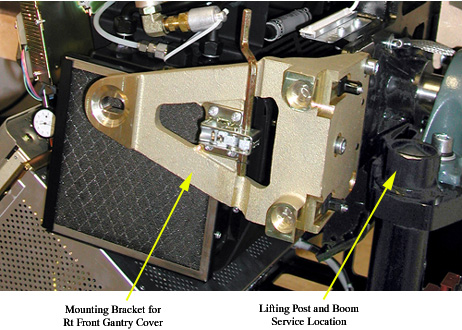
- Remove the M12 bolts holding mounting bracket for the right
front gantry cover and set the assembly aside. It may be necessary
to tilt the gantry back to remove the third bolt (not normally installed).
Figure 1. Mounting bracket for right front gantry cover and lift hoist service location
- Turn off the AXIAL DRIVE ENABLE, HVDC ENABLE, and 120VAC switches on the service switch panel.
- notice
- Turn off facility power to PDU and lockout/tagout according to lockout/tagout procedure.
- Position gantry so that the tube is positioned between 11 and 12 o'clock, and the HV Tank is at the 3 o'clock position.
- Free the HV cable.
- Carefully cut all tie-wraps securing HV cable. Note HV cable routing.
- Loosen the cable's locking ring.
- Pull cable terminal stick out of its receptacle on HV tank. Place tube crate cover over the HV cable stick. DO NOT lose the rubber sealing ring.
- Place a cap or enough paper towel in the newly created hole on the HV tank receptacle to prevent oil from leaking when you manually rotate the gantry to remove the tube.
- Manually rotate the Gantry until the X-Ray tube reaches the 3 o'clock position.
 warning
- Engage rotational lock.
- Measure, along top of the tube housing, the distance from the
edge of the ISO adjustment block to the rear edge of the tube housing.
See Figure 2.
Figure 2. Z-Alignment Measurement
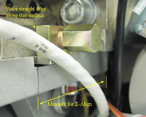
- Record the measurement. This will help put the new tube in roughly the same place, making alignments easier.
- Remove Power I/F board cover.
- Disconnect thermal sensor from Power I/F board at J7. Cut any tie-wraps holding the wires to the gantry.
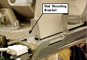
- Remove dial mounting bracket. See Figure 3.
Figure 3. Dial Mounting Bracket
- Disconnect anode stator cable from aux box.
- Remove 3 pin connector from aux box.
- Disconnect the clamp holding the cable to aux box. Keep the clamp, as you will need it for the new tube.
- Remove POR adjustment block and screw. Keep hardware.note:
Counting the number of rotations it takes to disengage the threads is helpful for installing the new tube near the same location as the previous tube (making alignments easier).
- Quickly disconnect the pump from the tube at the quick disconnect (QD). Align the pin with the slot on the QD and disconnect.
- Disconnect X-Ray tube from heat exchanger at quick disconnect.
- Insert the lifting post, boom, and chain hoist. Refer toFigure 1 for location.
- Disconnect Smart ID cable from Smart ID module (on tube).
- Connect hoist to tube lifting point. Newer model tubes (2005)
employ a single point lifting feature. For older tubes (pre-2005)
that must use a sling, connect the sling to the lifting hooks.
- Ensure that the sling / hoist joint is centered directly above the tube.
- Remove slack in hoist / chain / sling but do not over tighten. The tube should not move when the mounting bolts are removed.
- Remove the two bottom M12 mounting bolts, and then remove the upper bolts.
- Discard the mounting bolts and washers. The new tube comes with new mounting bolts.
- notice
- Place the tube in the crate for shipping. For more information, see the Performix Pro100 Tube Crate procedure.
 |
|
The HV cable's candlestick has a rubber sealing ring that must not be lost.
2 Install New Tube
Procedure
- Allow the tube unit to warm to room temperature before you install it.
- warning
- notice
- Place new tube near gantry so that you can attach the hoist to the hook(s) and use the hoist to lift the tube into place. For more information, see Performix Pro100 Tube Crate.
- With tube suspended, visually inspect the copper filter. The
primary copper filter is easily examined, since it is part of the
tube and visible. The copper filter should be clean, as well as dent
and scratch free:
-
If contamination is visible (see Figure 4), proceed to Collimator Cleaning Procedure Details.
-
If scratches or dust are visible, the copper filter must be replaced.
-
Discoloration is acceptable.
Figure 4. Extremely Contaminated Copper Filter

-
- Make a mark on the tube housing where the edge of the ISO adjustment block should be, according to your measurement in the removal process. See Figure 2.
- Attach adjuster screw from old tube to new tube.note:
If you counted the number of rotations for removal, insert screw the same number of rotations.
- Carefully swing the tube into place.
- warning
- notice
- Using the new mounting screws shipped with the tube, carefully
attach the new tube to the gantry. Make sure that the tube lies flat,
as it can be difficult to place properly. Using the hoist to control
the tube’s height can help greatly in mounting.
- warning
- Two versions of washers for the M12 bolts exist. Early versions
utilize a “pressure plate,” along with a lockwasher. Later
tubes ship with pre-assembled bolt / lockwasher / standoff pieces.
Refer toFigure 5 and Figure 6.
The pressure plates may NOT be used when counterbores are present OR with the standoff style washer shown Figure 6.
Figure 5. Pressure Plate - Correct Installation
Figure 6. Pre-assembled bolt / lockwasher / standoff
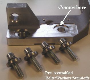
Installing the tube with either hardware combination is acceptable, but ensure that the hardware is installed correctly. The pre-assembled bolt combination may be used with or without counterbores present as long as the pressure plate is NOT installed. The tube crate may also contain more information.
- Finger tighten bolts.
- Disconnect hoist.
- Align with z-align measurement made during removal (pencil mark).
- Adjust M12 mounting bolts to pre-load torque specification.
Refer to Table 6.
- Apply final torque on all four M12 bolts according to the values
specified in Table 7.

- notice
- Disconnect sling and hoist from tube and boom.
- Remove the post and boom from the gantry.
- Disengage rotational lock.
- Connect the stator cable to the aux box. Use the clamp from the old tube to attach the exposed shield to the aux box.
- Connect both the pump AND the heat exchanger hoses to the tube.
- Using new hardware from tube crate, secure the quick disconnect
safety locking mechanisms. The torque spec. for the quick disconnect
safety mechanisms is 7.9 N-m (5.8 lb-ft, 70 lb-in, 81 kg-cm); however,
if the locking mechanism rotates in relation to the quick disconnect,
tighten slowly until it does not do so.note:
Do not severely overtighten the M6 bolts. Doing so can cause the quick disconnects to leak.
- Connect the thermal sensor to the Power Interface Board, J7.
- Reattach Power I/F board cover.
- Reattach the dial mounting bracket.
- Reattach the SMART ID cable.
- notice
- Rotate tube to 12 o'clock position.
- Connect the HV cable. See Securing HV Cable for more information.
- Reattach POR adjuster block.
- Connect Smart ID cable from power interface board to Smart ID module on tube.
- Check for oil leaks by rotating the gantry slowly.
- Manually rotate the gantry, at least one full revolution, and verify that no rubbing occurs.
- Tie-wrap all cables:
-
Stator cable
-
HV cable
-
Tube thermal switch
-
- Rotate tube to 2 o'clock position.
- Engage gantry rotational lock.
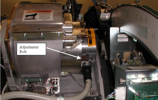
- Locate the focal spot drift adjustment bolt next to the high
voltage cable as shown in Figure 7. It is the only bolt that has a black washer under it.
Figure 7. Focal Spot Drift Adjustment Bolt
- notice
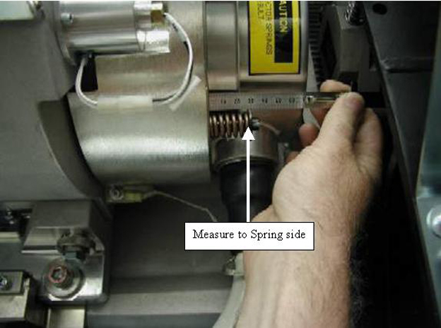
- Measure the length of the focal spot drift adjustment bolt spring with a small metric ruler or scale as shown in Figure 8.
Figure 8. Measurement of Focal Spot Drift Adjustment Bolt Length
- If the focal spot drift adjustment bolt length IS GREATER THAN
27mm, skip to Step 30. Otherwise, complete the following steps:
- Make a small reference mark on the outer side of the drift adjustment
bolt head with Whiteout/Liquid Paper or white paint shown in Figure 9.
Figure 9. Reference Mark on Focal Spot Drift Adjustment Bolt

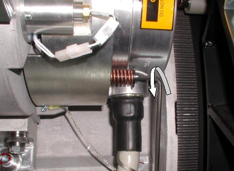
- Using a 5mm allen wrench, turn the focal spot drift adjustment
bolt 2 +/- 1/4 turns counter-clockwise as if you were looking down
on the bolt head, using the reference mark as shown in Figure 10.
Figure 10. Focal Spot Drift Adjustment Bolt Rotation
- Make a small reference mark on the outer side of the drift adjustment
bolt head with Whiteout/Liquid Paper or white paint shown in Figure 9.
- Disengage gantry rotational lock.
- Install the right gantry front cover bracket. Refer toFigure 1 in tube removal process.
- Restore system power at the main disconnect panel.
- Turn on gantry 120 VAC, HVDC ENABLE and AXIAL DRIVE ENABLE on the service switch panel. Press DRIVES RESET.
- After restart of software, begin entering the new tube information.
- Reset the system:
- Select SYSTEM RESETS.
- Select SCAN, then RUN.
|
|
|
|
|
3 Finalization
Procedure
- Checklist:
- New mounting bolts and washers are used for mounting the tube; old mounting bolts and washers are discarded.
- Proper torque specifications are followed for all fasteners (see “General Torque Cross Reference” in Torque Wrench Information)
- Tie-wraps and cables are in place.
- Perform Tube Installation Certification, Refer to SmarTube™ Setup
- Perform the following calibrations and checks:
- Gantry Rotation Safety Check
- Reset Tube TnT Data (Generator Tool)
- Plane of Rotation (POR)
- Beam on Window (BOW) Alignment
- CBF/SAG Alignment Process
- ISO Alignment Procedure
- Meter Verification (Pro16)
- HV Tank Feedback Resistor Verification
- Filament Calibration
-
HHS Scans
Tube Usage Information is found on the Common Service Desktop following path:
Error Logs>Tube Usage>Details
- Gantry Balance Procedure
- Hot ISO Alignment
- Put the Gantry Covers On.
- New Tube Configure
- Z-Slope
- DAS Gain Calibration
- Collimator Calibration
- Air Ratio Calibration.
- Detailed Cals
- FastCal
- System Scanning Test
- Quality Assurance Test
- Save System State