- Topic ID: id_11039035
- Version: 3.0
- Date: Apr 9, 2020 8:42:28 PM
ISO Alignment Procedure
Prerequisites
Cold ISO Alignment is done before the tube is heated by Generator calibrations. Hot ISO is done later.
Perform Tube Installation Certification, if needed. Refer to SmarTube Setup.
1 For Tube Change Only
Wait 90 minutes if the new tube had more than 25 Kilo Joules of energy input, [KV x mA x Sec ÷ 1000] within the last 30 minutes prior to the start of system alignments. If a tube heat soak has been performed you must wait a minimum of 6 hours before system alignments can be performed.
2 Confirm Cold Tube
When performing alignments, wait at least 15-30 minutes between scans to prevent unnecessary adjustments.
3 ISO Adjustment Procedure
Procedure
- You should be familiar with POR Alignment before proceeding with ISO alignment.
- Select Service –> Calibration, Run the ISO ALIGNMENTtool.
- Execute Air scan (small spot).
- Execute Air scan (large spot).
- Place the 1/8 inch screw driver on the phantom holder (should be pointing into the Z direction).
- Execute pin scan (small spot).
- Execute pin scan (large spot).
- CALCULATE ISO center alignment.
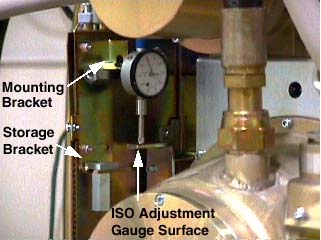
- Mount both dial indicators on the tube assembly - one for ISO
alignment and one for POR. (Figure 1.) Make sure that you zero both
of them (POR and ISO).
Figure 1. ISO Dial Gauge Mounting Location
- Loosen the 4 M-12 bolts on the tube assembly about 1/8 turn.
Loosening them more than 1/8 turn usually results in unpredictable movement while trying to align the tube.
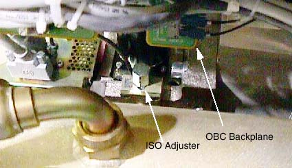
- Adjust the tube UP / DOWN as indicated by the calculation. The
adjustment bolt for ISO is located on the top of the tube - Please
see Figure 2.
While moving the tube in the ISO direction the tube will likely move POR out of alignment. By watching both dial indicators you can keep POR in alignment while moving ISO. Go slow - being accurate while moving the tube will reduce the number of iterations, because no unnecessary heat will be put into the tube.
Figure 2. ISO Alignment Adjuster
- Tighten the four (4) M12 bolts and verify dial gauge still reads the correct adjustment value.
- Adjust M12 mounting bolts to pre-load torque specification.
Refer to Table 3.
- Apply final torque on all four M12 bolts according to the values
specified in Table 4.
- Repeat steps 1 through 9.
- If the adjustments are within limit proceed to the next step, otherwise go to step 10.
- Wait 15 minutes, then recheck BOW to verify values are within
specification -1.5mm ±0.5mm.note:
For Brightspeed Select systems with a Solarix tube, the specification is -1.99 ± 0.5mm
-
If BOW is within spec, DO NOT adjust anything
-
If BOW is out of spec, alignments must be done, starting with POR and ending with BOW recheck.
-
4 Finalization
No finalization steps.