
- Discovery MR750 3.0T System Service Methods
- 5690009-2EN Revision 4
- 00000018WIA3074E030GYZ
- id_123738001.12
- Oct 11, 2021 3:47:40 PM
HP Z400 Computer Replacement
Prerequisites
| Required persons | Preliminary requirements | Procedure | Finalization |
|---|---|---|---|
| 2 | Not Applicable | 120 minutes | 30 minutes |
| Item | Quantity | Effectivity | Part number | Manufacturer |
|---|---|---|---|---|
| Screwdriver set | 1 | - | - | - |
| Item | Quantity | Effectivity | Part number | Manufacturer |
|---|---|---|---|---|
| See FRU manual. | As required | - | - | - |
| ||||
| Condition | Reference | Effectivity |
|---|---|---|
|
Host computer and GOCAA must be powered off. | - | - |
Procedure
- Remove the two screws that secure the left side panel.
Figure 1. Screws on Left Side Panel 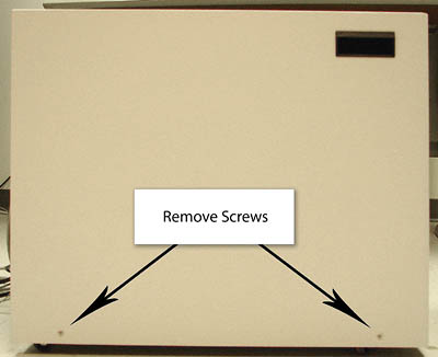 Note:
Note:The side panel has a short ground lead connecting it to the main chassis. When removing the side panel, do not strain this ground lead.
Figure 2. Left Side Panel Ground Lead 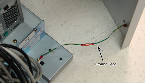
- Remove all the cables connected to the computer, ensure they
are properly labeled, and note their locations for reattachment.
Figure 3. HP Z400 Cable Configuration 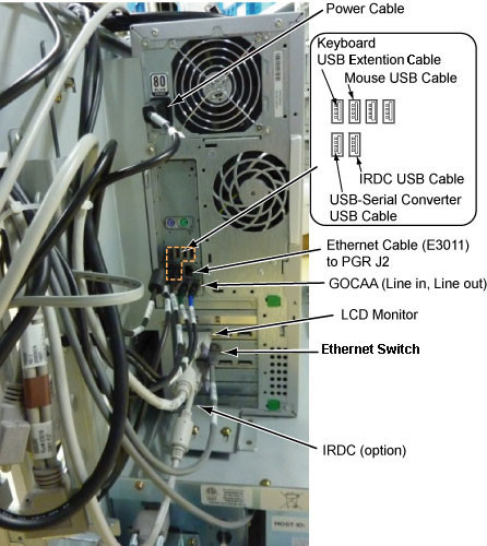
- Loosen the strap and remove the hook.
Figure 4. Removing Strap 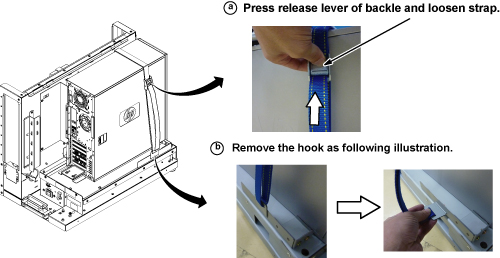
- Refer to the illustration below, and remove the Z400 computer
as follows:
- Loosen the two screws on the side slide plate, and slide the
plate in the direction of the arrow as shown below.
Figure 5. Removing HP Z400 Computer 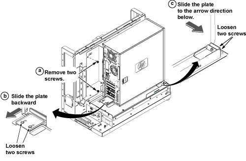
- Loosen the two screws on the side slide plate, and slide the
plate in the direction of the arrow as shown below.
- Remove the back bracket from the defective computer, and install
it on the new computer.
Figure 6. Installing Back Bracket 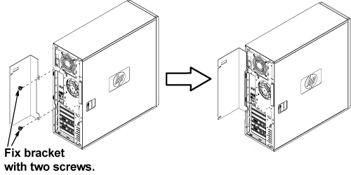
Position the computer as shown below.Notice Figure 7. Computer Placement 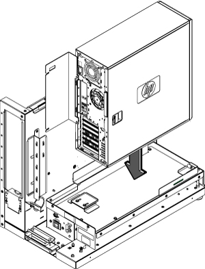
- To secure the computer:
- Attach the back bracket to the GOC frame with the two screws.
- Slide the back slide plate toward the computer until it aligns, and secure with the two screws.
- Slide the side slide plate toward the computer until it aligns, and secure with the two screws.
Figure 8. Securing Computer 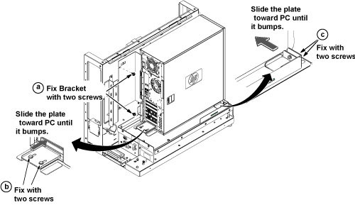
- Tighten the strap according as follows:
- Hook the bracket to the slot of the bottom plate.
- Pull and tighten the strap to secure the computer.
Figure 9. Tighten Strap 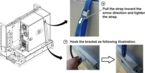
- Remove the dust filter from the old computer and attach it to
the new computer. If the old filter is not reusable, install a new
one.
Figure 10. Attaching Dust Filter 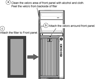
Finalization
- Remove LOTO from the PDU and the GOC. See the MR Service Safety Manual, PN 5452735.
- Restore power to the GOC.
Note:
If necessary, reconnect the optional UPS and ensure power is restored.
- Load software and applications onto the operating system. See Loading Host System Software (Quick Start). Note:
Load From Cold (LFC) must be performed to properly transfer customer options.
- Update the eLicense with the new Host ID. See Software Option Installation with eLicense Generated Keys.
-
Repackage the defective PC for return.Notice - Perform a scan to ensure the system and applications are working properly.