Discovery MR750w and SIGNA™ Architect T 3.0T System Service Methods
5690002-2EN
Revision
4
Object ID: 00000018WIA30EBF030GYZ
Topic ID: id_12374937 Version: 1.2
Date: Jul 5, 2019 10:03:32 PM
MNS Upconverter Replacement
Prerequisites
Table 1. Personnel requirements
Required persons
Preliminary requirements
Procedure
Finalization
1
5 minutes
30 minutes
10 minutes
Table 2. Tools and test equipment
Item
Quantity
Effectivity
Part number
Manufacturer
Non-Magnetic Tool
Kit
1
-
5112581
-
Table 3. Replacement parts
Item
Quantity
Effectivity
Part number
Manufacturer
MNS Upconverter
Module
1
-
5189655-2
-
Procedure
Perform LOTO on the PEN cabinet. See the MR Service
Safety Manual, PN 5452735.
Remove both of the rear pedestal side covers.
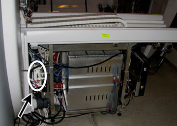
Locate the upconverter box, mounted on the front of the reroute
box in the rear pedestal.
Figure 1. Upconverter Box
CAUTION
Some cables are ferrous and are attracted to the magnet.
Disconnect and connect cables carefully.
When disconnecting cables, ensure ends do not become attached
to the magnet.
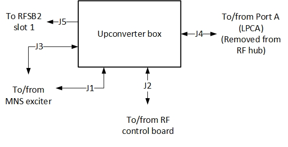
Disconnect cable connections from the upconverter box (viewing
from front of the rear pedestal).
Figure 2. Upconverter Cables
Remove the upconverter box from the rear pedestal and carefully
move it away from the magnet.
Note:
Place upconverter box outside of magnet room before completing
replacement procedure.
Mount the new upconverter box. For ease of installation in a
confined space, follow these suggestions:
Attach one mounting bracket to the reroute box and the other
mounting bracket directly to the MNS upconverter.
Approach the opposite side of the rear pedestal from where the
mounting was attached and slide in the MNS upconverter. Fully attach
the MNS upconverter to the reroute box.
Reconnect cables to the upconverter. See Figure 2 and Table 4 for cable connections.
Note:
On the RF control board, some cables may need to be disconnected
in order to properly connect the MNS upconverter cables. Reconnect
these cables after the upconverter is fully installed.
Table 4. MNS Upconverter Cable Connections
Cable Run Number
J# on MNS Upconverter
Connects to
Description
M1308
J3
J31 of Pen cabinet wall
MNS LO
M1309
J1
J33 of Pen cabinet wall
MNS loopback
M3356
J2
J11 - Slot 11 board of RF hub
Power and controls for MNS upconverter
[None]
J4
LPCA connector A
8W8 Rx signal input from connector A
[None]
J5
J8 of reroute box
8W8 upconverter signal output
Replace the rear pedestal side covers.
Notice
After LOTO is removed from the PEN cabinet, the Exciter board requires 20 minutes of power-up time before scanning.
Remove LOTO. See the MR Service Safety Manual, PN 5452735.