XFA Replacement (Mobile Site)
Prerequisites
1 Remove XFA
Procedure
- Remove L Upper Front Cover. Refer to SC Cover Removal.
- Drain the coolant. Refer to Draining Operation before replacing SRFD3 or XFA.
 warning
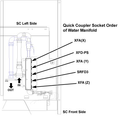
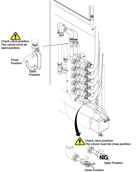
- Disconnect the IN and OUT quick couplers of XFA X, Y or Z from
the water manifold.
Figure 1. Water Manifold Socket Order
- caution
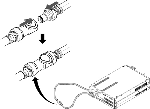
- Connect the IN and OUT of quick coupler, and tie the hose as
illustration.
Figure 2. Water Manifold
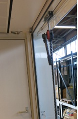
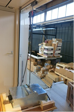
- Set the Universal Lift Hoist onto SC top. Refer to Hoist Setup.
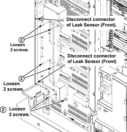
- Disconnect the two connectors of leak sensor assy.
- Remove the cabinet leak sensor assy by loosening 6 screws.
Figure 3. Remove Leak Sensor
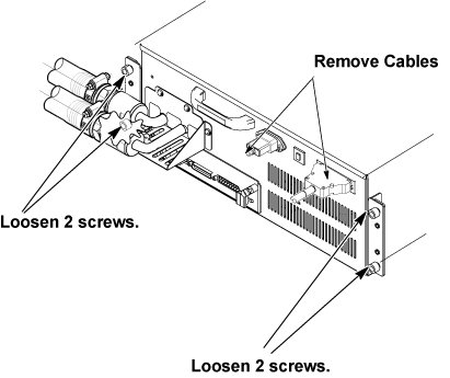
- Disconnect the all connectors and terminals from front panel of XFA.
- Loosen 4 screws tightening XFA front panel to the chassis.
Figure 4. Terminal Cover Removal and Loosening 4 Screws
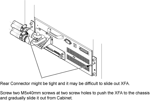
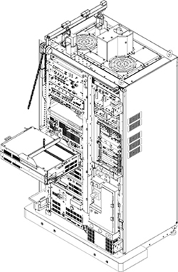
- Screw two M5 (40mm) screws at the two screw holes to push the
XFA to the chassis and gradually slide it out from Cabinet.
Figure 5. Gradually Slide Out Using Screws
 note:
note:M5 Screws to push out XFA are located at chassis as following illustration
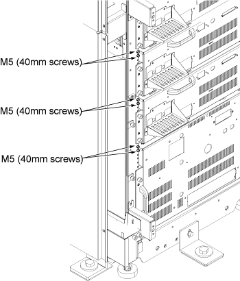 note:
note:If you cannot withdraw XFA using M5 screw, need to disconnect connector from rear side. Refer to In case connector of XFA or XFD-PS is very tight.
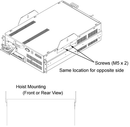
- Withdraw XFA from the chassis until hole of hoist bracket can be aligned to the hoist bar.
- Install the hoist brackets to the chassis of XFA with 4 screws.
Do not tighten 4 screws of hoist brackets.note:
Hoist Bracket is stored in FRU box.
Figure 6. Hoist Brackets Installation
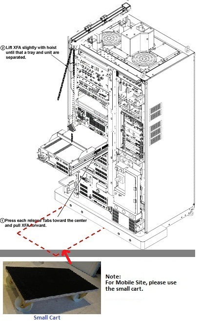
- Install the hoist assembly to the hoist brackets of XFA, and tighten 4 screws of hoist brackets. Check that hoist bracket and hoist assembly are installed surely.
- Using the hoist, apply tension to the lifting chain until the weight of the amplifier is supported by the hoist.
- Press the release tabs in on each side as you pull the unit
out further.
Figure 7. Hoist Operation
- notice
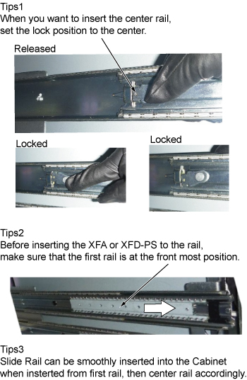
- Push the rail slider into the system cabinet before lowering
XFA. note:
Here is the tips of slider rail operation.
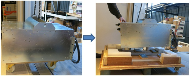
- Use the hoist and slowly lower the XFA Chassis to the floor.note:
When lowering the XFA Chassis, it may be easier to rotate XFA 90 degree as following illustration.
- Move the cart with XFA out of device room
- Install the hoist tool to the hoist point of trailer
Figure 8. Install the hoist tool to the hoist point of trailer
- Hoist the XFA from the hoist point of trailer and put onto
the top cover of XFA FRU package.
Figure 9. put onto the top cover of XFA FRU package
- Install the side covers on it
- Uplift and move the XFA with package out of the trailer.
- Remove the two hoist brackets from XFA chassis.
 |
|
 |
2 Install XFA (Mobile site)
Procedure
- Uplift and move the new XFA FRU with its arms (in side cover) to the hoist position on the trailer.
- Install Hoist tool to connect XFA and hoist point on the trailer.
- Hoist the XFA from the hoist point of trailer.
Figure 10. Hoist XFA
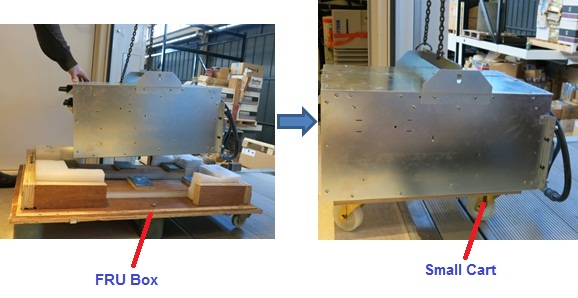
- Put the XFA onto the small cart in the operating room.
Figure 11. Put XFA to small cart
- Move the cart with new XFA to the equipment room
- Install XFA by the reverse order of the removal.note:
Make sure to connect all cables and hoses.
note:Make sure to close draining valves and open Supply and Return valves.
- Restore System Cabinet.
3 Finalization
Procedure
- Restore the Power. Refer to Lockout / Tagout for MDP(Main Disconnect Panel) or Facility PDU .
- Refill Coolant. Refer to Refill Coolant after replacement of SRFD3, XFA, or XFD-PS.
- To adjust DC Offsets, refer to DC Offset Adjustment.
- Perform [TPS Reset].
- Perform DQA Tool.
- Perform Signal to Noise - Head Scan.