Gradient Coil Replacement Coil Installation
Prerequisites
After having the fork lift truck remove the failed coil and cradle from the cart, the replacement body coil, on its cradle, must be loaded and taken to the scan room.
1 For Mobiles
The most difficult part of this procedure is getting the replacement coil correctly aligned so that it rolls easily and completely into the bore. A small carpenter's level is a useful tool to have at this point.
Procedure
2 REPLACEMENT COIL INSTALLATION
Procedure
 caution
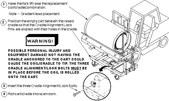
- Loading Replacement Coil on CartLoading Replacement Coil/Cradle on Cart
Figure 2. LOADING REPLACEMENT COIL/CRADLE ON CART
- Moving Coil into Magnet:
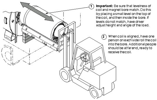
- Positioning Replacement Coil at Magnet
Figure 3. POSITIONING REPLACEMENT COIL AT MAGNET
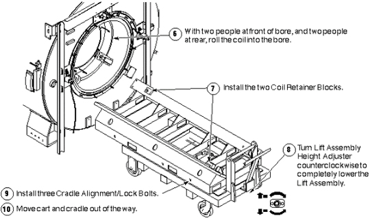
- Installing Replacement Coil
Figure 4. INSTALLING REPLACEMENT COIL
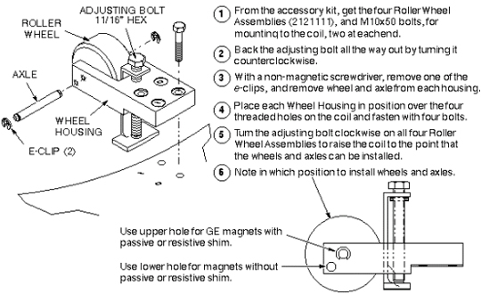
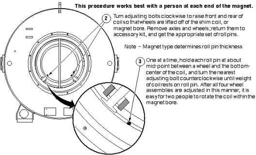
- Mounting the Roller Wheel Assemblies
Figure 5. MOUNTING THE ROLLER WHEEL ASSEMBLIES
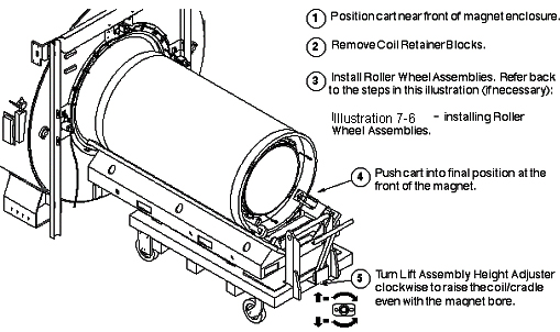
- Positioning Replacement Coil at Magnet
- Aligning the Coil in the Bore: Once the replacement coil is in the bore,
it must be aligned along the x, y, and z axes.
- Aligning the coil along the z-axis. See Figure 6 for the BRM Coil or Figure 7 for
the CRM Coil.
Figure 6. ALIGNING BRM COIL ALONG THE Z-AXIS
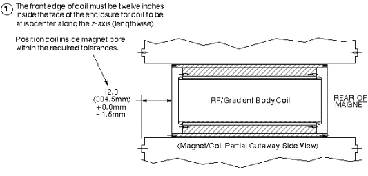
Figure 7. ALIGNING CRM COIL ALONG THE Z-AXIS
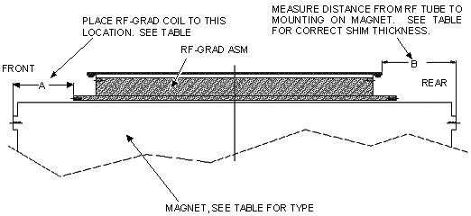
- Aligning the coil along the x-axis
Figure 8. ALIGNING THE COIL ALONG THE X-AXIS
The replacement gradient coil is now completely installed. At this point, you may follow either of two procedures:
-
If the RF Body Coil was removed for later installation in the replacement gradient body coil, perform the procedure to install RF coil below in Install RF Coil,
OR
-
If the RF Body Coil was replaced along with the gradient coil, go on to the following Connecting Replacement Coil.
- Aligning the coil along the z-axis. See Figure 6 for the BRM Coil or Figure 7 for
the CRM Coil.
 |
3 Install RF Coil
Procedure
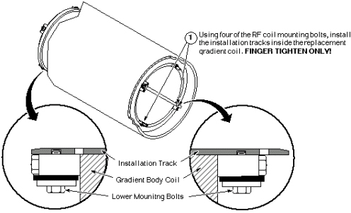
- Install Tracks in Replacement Gradient Coil
Figure 9. INSTALL TRACKS IN REPLACEMENT GRADIENT COIL
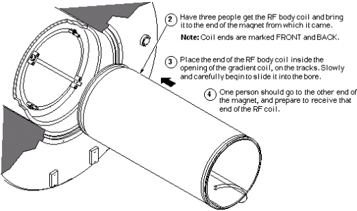
- Install RF Coil in Gradient Coil
Figure 10. INSTALL RF COIL IN GRADIENT COIL
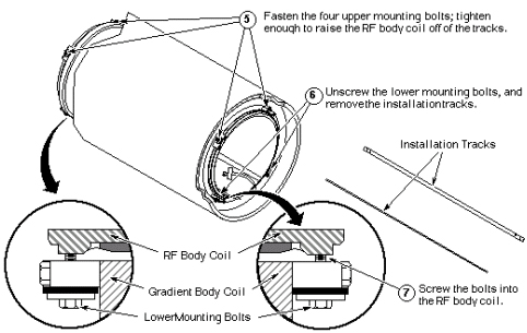
- Securing RF Coil in Gradient Coil
Figure 11. SECURING RF COIL IN GRADIENT COIL
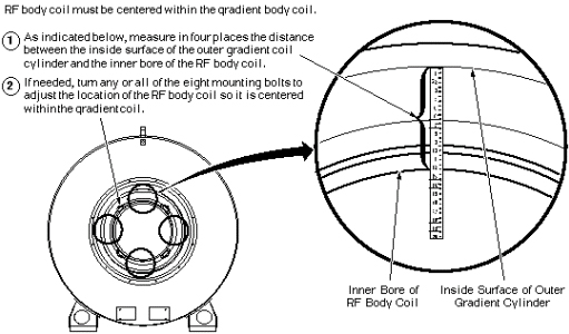
- Centering RF Coil in Gradient Coil
Figure 12. CENTERING RF COIL IN GRADIENT COIL
4 Connecting Replacement Coil
Procedure
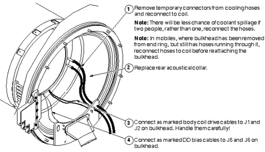
- Reconnect Cooling Hoses, Acoustic Collar, and Power
Figure 13. RECONNECT COOLING HOSES, ACOUSTIC COLLAR, AND POWER
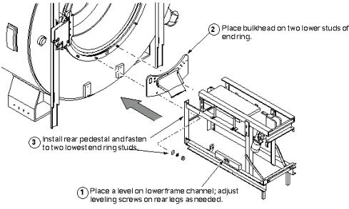
- Reinstall Rear Pedestal (in Mobiles only)
Figure 14. REINSTALL REAR PEDESTAL (IN MOBILES ONLY)