Spike Noise Check
Prerequisites
1 Hardware Preparation for Spike Noise Data Collection
Procedure
- Remove the front panel from the Systems Cabinet.
- Disable the RF Output from the RRF Master Exciter by setting the RF Out toggle switch (located on the RRF front panel I/O board) to the Disable position.
- Set the oscilloscope to 1M ohm impedance.
- Connect the oscilloscope power plug to the service outlet of the system cabinet to prevent ground loops that may cause higher floor noise. .
- Set up the oscilloscope as follows:
- Channel 1 - 5 mV/div, 1 mW input
- Channel 2 - 5 V/div, 1 mW input
- Time Base - 5 msec/div
- Trigger - auto, external
2 Spike Noise Scan Preparation
Procedure
- At the operator workspace, select the Scan icon on the desktop control panel.
- If necessary, exit out of any previous exams by selecting [End Exam].
- Click on New Pt and enter the following:
- ID: geservice
- Name: spike noise
- Weight (lb.): 111
- Remove all phantoms from the patient table. This is an empty bore test.
- Place the head coil without a phantom on the cradle. Landmark on the center of the head coil. At the keypad on the front magnet enclosure, press LANDMARK, and MOVE TO SCAN.
- The following three steps are proprietary and only available for GE
use, and to sites with a valid Advanced Service Package Limited License. The
non-proprietary procedure is listed after these steps.
- Set Patient Protocols to Service.
- Select the scan protocol by clicking on Other, select the Spike Noise protocol and series 1 from the menu then click [Accept] to load the Spike Noise (Head Axial, A-P) protocol.
- Click on Accept to load the protocol.
- Click on Save Series and then Prepare
to scan, then press Move to Scan.note:
Use Series 2-8 per later procedure steps.
3 Sample Noise Data Collection and Analysis
Procedure
- Click on Manual Prescan and set R1=11, R2=15, TG=0.
- Press the PAUSE SCAN button on the console keyboard.
Press the FAN ON button on the magnet enclosure to turn
off the patient comfort fan (the fan turns on automatically with scan software).note:
Ignore the first 30 seconds of data.
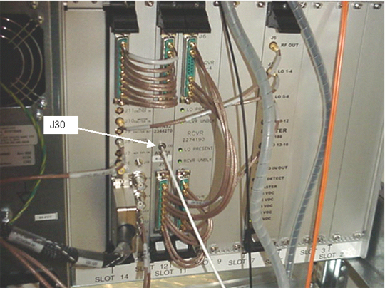
The MGD/RRF are now in the receive mode and any noise can be observed at the UTNS J30 receiver 1 port. Scope must be in auto trigger mode.
- Put the scope in continuous acquisition mode. The method for doing this will vary with scope type. Clear the oscilloscope display and ensure the trigger is in the auto position.
- Observe the scope display for about two minutes. The noise envelope
(channel 1) is typically 45-50 mV p–p. Verify that there are no spikes >0.5
Nenv (where Nenv is the noise
envelope peak to peak value) above the noise envelope. See Figure 3.
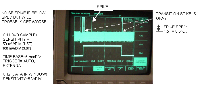
Figure 3. SPIKE NOISE SCOPE WAVEFORM (PAUSED PRESCAN)
 note:
note:Ideally, there should be no spikes beyond the envelope. Any spikes present indicate that a connection is loose, or a component is bad (e.g., intermittent connection of power cable to a shield cooler cold head, or copper fingers on exam room door are damaged). Noise spikes that are greater than the spike spec create images with corduroy-like artifacts. Noise spikes that are presently less than the spike spec will probably get worse over time.
note:If there are no spikes present, and you are in doubt whether the setup is working, you can simulate an RF leak by opening the exam room door, or by turning the room lights on or off if the site is RF quiet. Clear the oscilloscope display and observe the new waveform on the display. You should now see noise spikes beyond the waveform envelope. Don't forget to close the exam room door when you are finished.
- Press the FAN ON button on the magnet enclosure to turn on the patient comfort fan. Clear the oscilloscope display and ensure that the trigger is in the Auto position. Observe the oscilloscope display for about two minutes. The noise envelope (channel 1) should remain as described in Step 4 above.
- Clear the oscilloscope display and change the trigger from Auto to Normal.
- Press the FAN ON button on the magnet enclosure to turn off the patient comfort fan.
- Press the START SCAN button on the console keyboard to resume prescan. Click on Scan T/R.
- Observe the scope display after two minutes. The noise envelope (channel
1) should be approximately 50mV (1.5T) or 130mV (3.0T). Verify that there
are no spikes >0.5 Nenv (where Nenv is
the noise envelope peak-to-peak value) above the noise envelope in the region
of interest (except for the beginning and end transition spike). See Illustration
1-4.
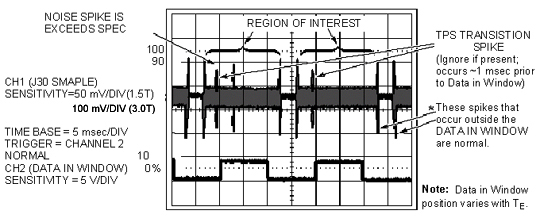
Figure 4. SPIKE NOISE SCOPE WAVEFORM (PRESCANNING)
 note:
note:The Region of Interest extends beyond when the observed Data In Window signal is high because the Data In Window position varies with TE. The Transition Spike (not always present) occurs when the RF subsystem transitions from transmit to receive frequency; it occurs ~1 msec prior to the Data In Window. (The frequency transition point can be confirmed by viewing the DDS OUT signal on the Exciter Board.)
note:If the spike noise appears only during prescan, the problem is more likely to be a loose connector, freely hanging cables near the magnet, poorly soldered components, or coil mounting hardware. Anything that is subject to vibration from gradient activity should be investigated.
- Click Done.
- Click on New Series. Set up scan prescription for series #2 scan per notes and Table 4, then repeat steps Sample Noise Data Collection and Analysis .
- Repeat the previous step until all head prescans (series #1 through #4) have been completed
4 Image Data Collection/Analysis
Procedure
- Disconnect the oscilloscope from J30 on the RRF UTNS and restore all cables to their normal configuration.
- Reset the RF Out switch on the RRF Front Panel I/O board to the Enable (left) position.
- Install the front cover panel on the Systems Cabinet.
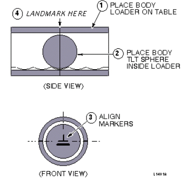
- Setup using SPT Loader: Position the SPT body loader and TLT sphere
on the table and landmark per Figure 5.
Figure 5. SPT BODY LOADER AND TLT PHANTOM SETUP
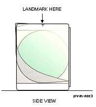
- Setup using Long Body Loader. Position the body TLT sphere in the center
of the long body loader and landmark per Figure 6
Figure 6. LONG BODY LOADER AND TLT PHANTOM SETUP
- Click on New Series and Last Series from the procedure in Spike Noise Scan Preparation.
- At the front enclosure, press LANDMARK, then MOVE TO SCAN.
- Click on Save Series, then Prepare to Scan.
- Click on Scan (system auto prescans first).
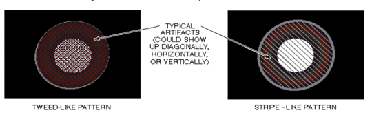
- Display and examine each of the twenty images for tweed-like or stripe-like artifacts. See Figure 7. If artifacts are present, use the procedures described in the EPI White Pixel Troubleshooting Guide to troubleshoot the system.
Figure 7. TLT SPHERE WITH TYPICAL ARTIFACTS
5 What to do next
Finalization
No finalization steps.