
- SIGNA MR355 / SIGNA MR360
- Service Manual
- 5856356-3EN Revision 5.0
- Basic Service Documentation. Copyright General Electric Company.
- 00000018WIA302CAF20GYZ
- id_131071141.3
- Jul 5, 2019 10:46:04 PM
Signal To Noise Check-Surface Coils
Prerequisites
| Required persons | Preliminary requirements | Procedure | Finalization |
|---|---|---|---|
| 1 | - | - | - |
| Item | Quantity | Effectivity | Part number | Manufacturer |
|---|---|---|---|---|
| Universal Phantom Holder | 1 | - |
46-328383P1 | - |
| 100mm Sphere Phantom (filled with NiCl2 solution) | 1 | - |
46-317586G1 | - |
| TLT Head Sphere Phantom (filled with NiCl2 solution) | 1 | - |
46-265826G6 (for Flex Coil) | - |
| · Head Loader | - | - |
46-287899G1 (for Flex Coil) | - |
| ||||
| Condition | Reference | Effectivity |
|---|---|---|
|
No image artifacts | - | - |
| - | - |
About this task
Note:
The Body SNR Sphere Phantom, 46-265635G4, is not provided with the System. If the Body SNR sphere is needed, the customer must order it. A Body Loader is provided with the system.
Procedure
- For Coils using the Universal Phantom:
- Position the Universal Phantom Holder on the coil. Refer to Figure 1 for specific details for each coil type.Note:
The General Purpose (GP) Flex Coil uses the Head Coil TLT phantom and loader for its phantom (not the Universal Phantom). Refer to Step 8 for General Purpose (GP) Flex Coil setup details.
Figure 1. UNIVERSAL PHANTOM HOLDER SETUP 
- Place the 100-mm phantom in the phantom receptacle, LANDMARK, and MOVE
TO SCAN. See Figure 2.
Figure 2. LANDMARKING UNIVERSAL PHANTOM 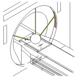
- Position the Universal Phantom Holder on the coil. Refer to Figure 1 for specific details for each coil type.
- GP Flex Coil Setup: Set up Flex Coil per Figure 3. LANDMARK, and MOVE TO SCAN.
Figure 3. GP FLEX COIL PHANTOM SETUP 
Finalization
No finalization steps.