
- SIGNA MR355 / SIGNA MR360
- Service Manual
- 5856356-3EN Revision 5.0
- Basic Service Documentation. Copyright General Electric Company.
- 00000018WIA30310030GYZ
- id_131076361.3
- Jul 5, 2019 10:46:05 PM
Rear End Bell Removal
Prerequisites
| Required persons | Preliminary requirements | Procedure | Finalization |
|---|---|---|---|
| 4 minumum | - | - | - |
| Item | Quantity | Effectivity | Part number | Manufacturer |
|---|---|---|---|---|
| 12-inch length of 1/2-inch I.D. hose | 1 | - | - | - |
| 2 hose clamps for 1-inch O.D. hose | 1 | - | - | - |
| 4-inch-long piece of copper tubing, 1/2-inch O.D. | 1 | - | - | - |
| Roll of paper toweling | 1 | - | - | - |
| Pair of latex gloves | (optional) | - | - | - |
| Non-magnetic torpedo level or similar | 1 | - | - | - |
| Epoxy-filled Gradient Coil cart (2134810), cradle (2134810-2), and accessory kit (2134810-4). | 1 | - |
2144093 | - |
| Class 1 electric rider lift truck, 4-wheel, rated at 6000 lbs (in case the coil, cart, and cradle must all be lifted together— a necessity in mobiles); with forks a minimum of 56 inches long; with side shifter for easy width adjustment and lateral movement of forks. | 1 | - |
n/a | - |
| Non-magnetic tool kit | 1 | - |
46-320273G1, G2, G3, or G4 | - |
| ||||
| Condition | Reference | Effectivity |
|---|---|---|
|
Verify that the Epoxy-filled Gradient Coil accessory kit contains all the parts listed in Kit Contents. | - | - |
|
Remove bridge first - Bridge must be removed before you can remove either end bell. | - | - |
Procedure
- Removing Rear Patient Comfort:Note:
Microphone and speaker cables in mobiles - If you're working in a mobile, these cables will have already been removed prior to the removal of the rear pedestal.
Note:Equipment damage possibility. Hold Patient Comfort Module in place while removing the two screws that secure it. The alignment pins can break if too much downward stress is applied.
Figure 1. REMOVE FRONT PATIENT COMFORT ITEMS 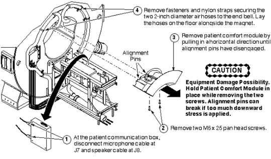
- Disconnecting Incoming Power:
Figure 2. DISCONNECT INCOMING POWER 
- Removing Rear End Bell:Note:
Possible equipment damage. When moving the Body Coil Drive Cables (usually colored blue), handle them with care. Do not kink them, or bend them sharply; damage can occur.
Figure 3. REMOVING REAR END BELL 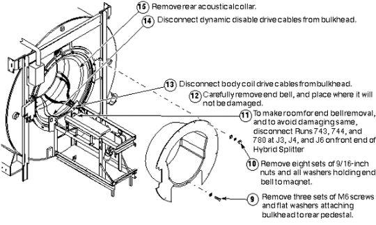
- Disconnecting Cooling System:
CAUTION Notice Notice Note:Anti-freeze in coil - Depending on coolant hose length, the gradient coil assembly, hoses, and heat exchanger may hold as much as five gallons of coolant. Thirty-five percent of this is anti-freeze, which prevents the ionized water from freezing when the coil is shipped. When the hoses are removed from the coil, approximately two gallons of coolant remain in the coil.
Note:Four hands are better than two - While it is possible for one person to disconnect the coolant hoses at the rear of the body coil, it is easier if two people do it, and there is less chance of spilling the coolant.
Note:Disconnecting Cooling System: Steps 1–3Rear bulkhead in mobiles - In mobiles, where bulkhead has been removed from end ring, you might choose to slide the hose ends out of the bulkhead before connecting the ends together.
Figure 4. DISCONNECTING COOLING SYSTEM: STEPS 1–3 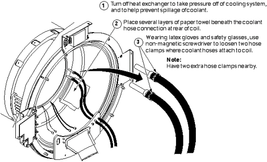 Note:
Note:Four hands are better than two - While it is possible for one person to disconnect the coolant hoses at the rear of the body coil, it is easier if two people do it, and there is less chance of spilling the coolant.
- Disconnecting Cooling System: Steps 4–8
Figure 5. DISCONNECTING COOLING SYSTEM: STEPS 4–8 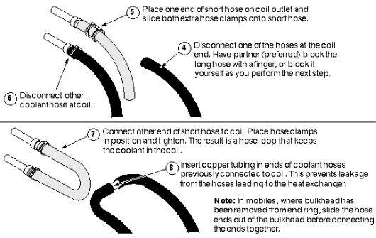
Finalization
No finalization steps.