
- SIGNA MR355 / SIGNA MR360
- Service Manual
- 5856356-3EN Revision 5.0
- Basic Service Documentation. Copyright General Electric Company.
- 00000018WIA30AD8E20GYZ
- id_131071803.0
- Aug 29, 2019 1:42:30 AM
Probe/SV Calibration and SNR Tests
Prerequisites
| Required persons | Preliminary requirements | Procedure | Finalization |
|---|---|---|---|
| 1 | Not Applicable | 30 minutes | Not Applicable |
| Item | Quantity | Effectivity | Part number | Manufacturer |
|---|---|---|---|---|
| MRS Phantom without the loader | 1 | - |
2152220 | - |
| Condition | Reference | Effectivity |
|---|---|---|
|
Fully operational 1.5T or 3.0T Signa EXCITE system with all performance specifications met. | - | - |
|
Magnet is shimmed and acceptance specifications have been met. | - | - |
|
Grafidy 3 has been performed and all acceptance specifications have been met. | - | - |
About this task
The PROBE options have changed for systems with 11x or newer software. Prior to 11x, both PROBE-P and PROBE-S options were included with Catalog M1033JD. After 11x the PROBE-P and PROBE-S options were separated. Parts of the calibration procedure will only apply to the option(s) you have. The two catalogs being used are:
-
PROBE-P option is now part of M3090MA and M3333WG
-
PROBE-S option has a separate Catalog of M3333WH, which will also include PROBE-P
BREASE option (M3335KK) also requires PROBE-P calibration (Probe/P Tuning)
Overview
About this task
This material applies to 1.5T Signa EXCITE systems as well as Signa 3.0T EXCITE systems and describes two separate hydrogen ONLY spectroscopy (Probe/SV) procedures:
-
Echo Peak Location Calibration (automated Probe Tuning script) for BRM and TRM ONLY (the calibration should not be run for CRM systems)
-
Probe SNR performance test for all systems (BRM, TRM, and CRM)
The Tuning procedure determines the values of control variables (CVs) that are necessary for Probe/SV scanning. Each Tuning scan will result in 18 coordinate values (three sets of six). Within each set of six, the first four values are described as A, C, B, and D. The 5th is E or - Verification, and the 6th is F or + Verification. Additional calculations (using the first four values of each set) are performed, and the resulting values will be automatically entered into a calibration file producing site specific Control Variables. The SNR procedure will be performed after the Tuning procedure.
Probe/SV Tuning Procedure (Echo Peak Location Calibration)
BRM Only - Probe/S Tuning Procedure (Option M3333WH only)
Procedure
BRM ONLY - Probe/P Tuning Procedure
Procedure
TRM Only - Probe/S Tuning Procedure (M3333WH only)
Procedure
TRM ONLY - Probe/P Tuning Procedure
Procedure
Probe/SV SNR Procedure
About this task
-
The MRS Phantom (without the loader) must be used for the SNR procedure. The greenest value of temperature strip must be entered as a Control Variable (tempC).
-
In the TwinSpeed (TRM), there are two gradient modes, WHOLE and ZOOM. The procedures should be repeated for both. Start with WHOLE, finish, and than restart with ZOOM mode.
Probe-S SNR Procedure (M3333WH only)
Procedure
Probe-P SNR Procedure
Procedure
Help
About this task
This section contains Illustrations of Probe SNR Spectra, both incorrectly tuned and correctly tuned to familiarize the user with what a good spectrum looks like. During tuning or SNR troubleshooting, it may be necessary for a site to back up the original echoloc.dat file. This backup process requires renaming the file, otherwise, it will be overwritten during the tuning calibration. Additional information can be obtained concerning the cause of an AWS (Auto-Water Suppression) failure by logging the messages generated during the Probe APS. A site may be required to send Probe SNR raw data to an expert for review. This section explains the P raw file location process and how to transfer it.
Example SNR Spectra
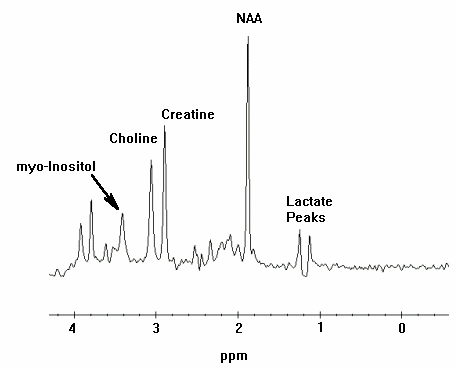
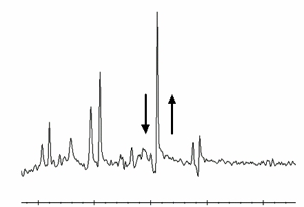
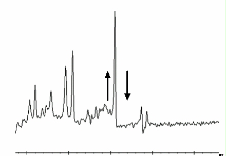
About this task
Errors in the Probe Tuning Calibration Procedure can introduce changes in the appearance of the resulting Probe SNR spectra. This section contains example spectra from a Probe-P SNR protocol using the MRS phantom. Figure 1 shows a correctly-tuned spectra. Pay particular attention to the base (left and right) of the NAA (NA) peak; this is the largest peak located at the center of the spectrum.
Procedure
Directory Creation
Procedure
P Raw Data File Location
About this task
This portion of the procedure should be performed after running a Probe SNR protocol to facilitate P raw file identification.
Procedure
What to do next
Finalization
No finalization steps.