
- SIGNA MR355 / SIGNA MR360
- Service Manual
- 5856356-3EN Revision 5.0
- Basic Service Documentation. Copyright General Electric Company.
- 00000018WIA30D17F20GYZ
- id_131066661.4
- Jul 6, 2019 12:03:28 AM
Low Height Fixed Table Installation
Prerequisites
| Required persons | Preliminary requirements | Procedure | Finalization |
|---|---|---|---|
| 1 | Not Applicable | 30 minutes | Not Applicable |
| Item | Quantity | Effectivity | Part number | Manufacturer |
|---|---|---|---|---|
| Standard Tool (Non-Magnetic) | 1 | - | - | - |
| ||||
About this task
Overview
This procedure describes how to install Low Height Fixed Table.
Procedure
- Fix the Table to the dock frame using four bolts. The screw
type is 1006-M10C025-31.Note:
Align the Table and Dock Frame by adjusting the 4 wheels.
Note:Do not tighten the screws too tight now since Table adjustment will be performed later.
Figure 1. Dock Mounting Support Installation 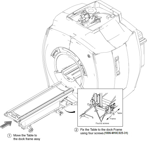
- Connect all cables.
-
Connect 5453341–J2 to 5447902–J2
-
Connect 5436192–J1 to 5443864–J1
-
Connect 5447902–J2 to Table Control Box J3
-
Connect 5443864–J1 to Table Control Box J4
-
Ground Cables (x2)
-
Connect DC Cable Assy(5346920) to Run# M1509 (from Mega SW)
-
Coaxial Cable Assy (5346919) to Run# M3511 (from Mega SW)
Note:Make sure the following cables are already connected to Table Control Box.
-
RUN421 to Table Control Box J1
-
RUN#2009 (MG2-A29-J1) to Table Control Box J2
Figure 2. Cable Wiring 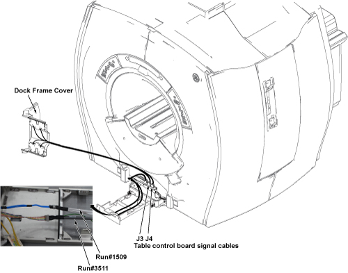
Figure 3. Wiring Diagram 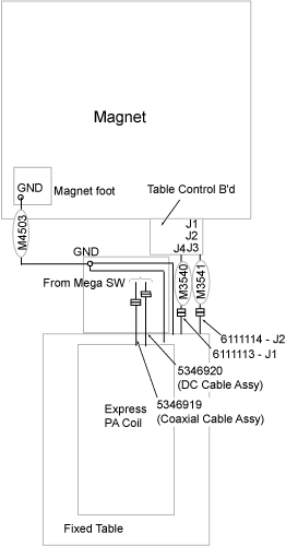
Figure 4. Cable Wiring Detail 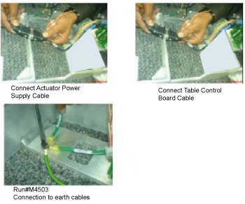
-
Finalization
No finalization steps.