Basic Service Documentation. Copyright General Electric Company.
Object ID: 00000018WIA302CDF20GYZ
Topic ID: id_13106057 Version: 3.0
Date: Feb 22, 2021 9:54:01 PM
LOTO Global Operator Console / Operator Workspace
Prerequisites
Table 1. Personnel requirements
Required persons
Preliminary requirements
Procedure
Finalization
1
Not Applicable
10 minutes
Not Applicable
Table 2. Tools and test equipment
Item
Quantity
Effectivity
Part number
Manufacturer
Brass Master Padlock with Brass Shackle
2
-
46-194427P320
-
Red LOTO Personal Lock Wrap
1
-
2393068
-
Multi-Locking Device (if multiple service personnel are involved)
1
-
46-194427P313
-
Red Warning LOTO Tag
1
-
46-194427P322
-
About this task
Warning
Electrocution hazard
High voltage present.
Use proper LOTO procedures before servicing and/or maintaining.
Prior to performing work on the Global Operator Console (GOC) or items in the Operator Workspace, a LOTO-authorized GE Field Engineer (FE) must perform the steps in this Lock Out / Tag Out (LOTO) Procedure. Completing all steps in this procedure ensures a safe environment when working on these parts.
Table 3. Details of Procedure
Name of equipment
Number of locks
Titles of employees authorized to perform LOTO
Titles of affected employees
How to notify
Host PC and operator’s workspace equipment
1 per GE FE
GE FEs
Hospital Personnel
Verbal, Posted signs
Energy source
Yes
No
Location of energy isolating means
Magnitude of energy
Electrical
x
Power Distribution Unit (PDU) circuit breaker panel
120VAC
Pneumatic
x
Hydraulic
x
Gas/Water/Steam
x
Chemical
x
Mechanical Motion
x
Gravity
x
Springs
x
Thermal
x
Stored Energy
x
Air Under Pressure
x
Oil Under Pressure
x
Water Under Pressure
x
Gas Under Pressure
x
Steam
x
Other
x
PDU with Plastic breaker Cover- Sub-System Lockout
Procedure
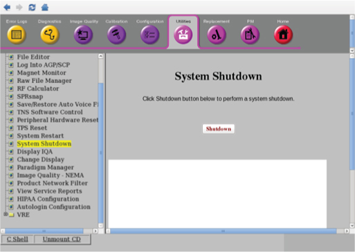
From the Common Service Desktop, select Utility > System Shutdown and click Shutdown.
Figure 1. System Shutdown
Confirm that the GOC is shutdown.
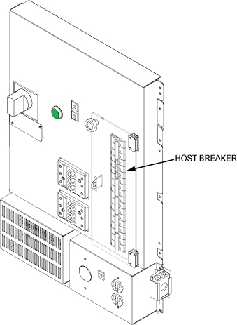
Open plastic Cover. Remove power to the Operators Workspace by shutting off the HOST breaker on the front of the PDU.
Figure 2. Breaker locations on PDU
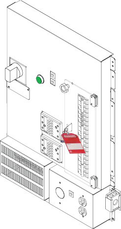
Lock and Tag the Breaker Panel on the PDU.
Figure 3. Lock and Tag the Breaker Panel
PDU with Plastic breaker Cover- Sub-System Lockout - Restoring Power
Procedure
Alert necessary personnel that power is being re-applied.
Remove the lock and the tag.
Open plastic door over the front of the PDU breakers and switch on HOST Breaker on the PDU.