
- SIGNA MR355 / SIGNA MR360
- Service Manual
- 5856356-3EN Revision 5.0
- Basic Service Documentation. Copyright General Electric Company.
- 00000018WIA30601030GYZ
- id_131066861.3
- Jul 5, 2019 11:18:59 PM
LCC Dock Replacement
Prerequisites
| Required persons | Preliminary requirements | Procedure | Finalization |
|---|---|---|---|
| 2 | Not Applicable | 1 hours | Not Applicable |
| Item | Quantity | Effectivity | Part number | Manufacturer |
|---|---|---|---|---|
| non-ferrous adjustable wrench | 1 | - | - | - |
| non-ferrous flathead screwdriver | 1 | - | - | - |
| socket wrench | 1 | - | - | - |
| allen screwdriver | 1 | - | - | - |
| ||||||||
About this task
Procedure for replacement of the following dock components for 1.5T and 3.0T LCC Magnets.
-
The dock limit switch board.
-
The dock gear-motor and clutch assembly.
| Last Revised: | April 30, 2007 |
Removal of Dock
Procedure
Perform ACGD Lock Out Tag Out.DANGER 
- Using a marker, mark the nut and clamp bracket before removal.
The marks will be realigned when the dock is installed later to ensure
proper tightening. See Figure 1.
Figure 1. Marking the Nut and Clamp Bracket 
- Loosen the bolts attaching the dock assembly at the front and
at the right and left brackets. See Figure 2. (Figure 5 also shows
bolt locations).
Figure 2. LOOSEN DOCK ATTACHMENT BOLTS 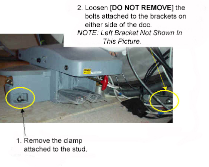
Applying pressure to the top of the dock, completely remove all dock attachment bolts. See Figure 3.Warning 
Figure 3. APPLY PRESSURE TO DOCK AND REMOVE ATTACHMENT BOLTS 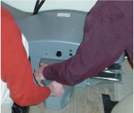
- Use two FEs to pull the dock away from the magnet until the
stud in the front is hitting the inner frame. See Figure 4.
Figure 4. PULL THE DOCK AWAY FROM THE MAGNET AS MUCH AS POSSIBLE 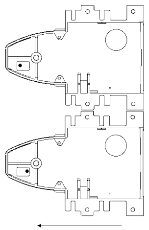
Use two FEs to lift the dock up JUST ENOUGH to clear the top of the stud in the floor. See Figure 5.Warning 
Figure 5. LIFT THE DOCK JUST ENOUGH TO CLEAR THE STUD IN THE FLOOR 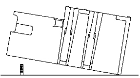
- The two FEs should gently place the dock to the left side of
the stud in the floor while still maintaining vertical downward pressure
to the dock. See Figure 6.
Figure 6. PLACE DOCK DOWN TO THE LEFT OF THE STUD IN THE FLOOR 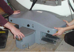 Note:
Note:It should not be extremely difficult for two FEs to pull the dock away from the magnet once all bolts are removed. If you do encounter difficulty, check that the brackets are not caught against the front of the magnet. See Figure 7.
Figure 7. WATCH FOR INTERFERENCE BETWEEN THE BRACKET AND THE MAGNET 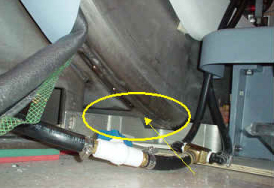
Replacement of Dock Limit Switch
Procedure
- To remove the Dock Control Assembly, see Figure 8.
Figure 8. REMOVAL OF THE DOCK CONTROL ASSEMBLY 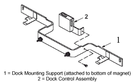
- To access the circuit board internal to the Dock Control Assembly,
see Figure 9.
Figure 9. REMOVAL AND REPLACEMENT OF DOCK LIMIT SWITCH BOARD 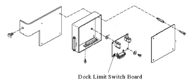
- Note:Re-attach the assembly to the Dock Mounting Support.
Realign the marks on the nut and clamp bracket when installing the dock. This is to ensure proper tightening.
Excessive tightening may result in the stud being pulled from the floor.
Replacement of Gear Motor and Clutch Assembly
Procedure
The Motor and Clutch Assembly should only be removed AFTER completing the procedure for Removal of Dock, refer to Removal of Dock.Warning - Remove the upper cover of the dock by un-bolting the four hexbolts.
See Figure 10.
Figure 10. REMOVE FOUR HEXBOLTS FROM UNDER DOCK COVER 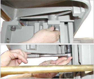
- Disconnect the motor's ground lug from the cover. See Figure 11.
Figure 11. MOTOR GROUND LUG REMOVAL 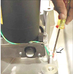
- Remove the four mounting screws for the motor. See Figure 12.
Figure 12. REMOVE MOTOR MOUNTING SCREWS 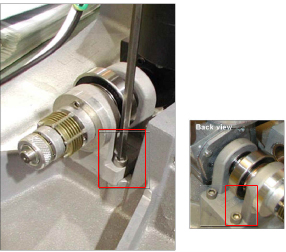
Installation of Dock
Procedure
With two field engineers, one holding each side of the dock, enter the magnet room and place the dock on the floor where the foot of the patient table would normally be located.Warning - While maintaining pressure to the top of the dock, position
the dock against the base of the magnet to the left of the floor stud
at the front of the dock. See Figure 13.
Figure 13. Placement of Dock 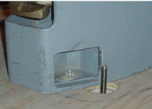
- Lift the dock just enough to clear the top of the stud in the
floor. See Figure 14.
Figure 14. Lifting Dock to Clear Floor Stud - Note:Use the attachment bolts to secure the dock at the front stud and side brackets. See Figure 15.
Realign the marks on the nut and clamp bracket when installing the dock. This is to ensure proper tightening.
Excessive tightening may result in the stud being pulled from the floor.
Figure 15. SECURE THE DOCK TO THE MAGNET 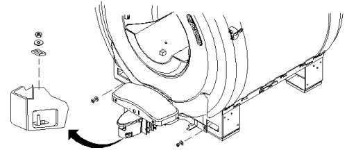
What to do next
Finalization
No finalization steps.