
- SIGNA MR355 / SIGNA MR360
- Service Manual
- 5856356-3EN Revision 5.0
- Basic Service Documentation. Copyright General Electric Company.
- 00000018WIA30751F20GYZ
- id_131075703.0
- Aug 29, 2019 1:53:27 AM
HD 8CH Body Coil Cable Replacement
Prerequisites
| Required persons | Preliminary requirements | Procedure | Finalization |
|---|---|---|---|
| 1 | 0 minutes | 30 minutes | 0 minutes |
| Item | Quantity | Effectivity | Part number | Manufacturer |
|---|---|---|---|---|
| Screw Driver Set | 1 | - | - | - |
| Item | Quantity | Effectivity | Part number | Manufacturer |
|---|---|---|---|---|
| FRU Cable Assembly (P/N: 2417162), GE Signa HD 1.5T 8CH Body Array Coil | 1 | - | - | - |
About this task
Follow this process to replace the cable assembly on the 1.5T Signa HD 8CH Body Array Coil (P/N: 2415366) by GE/USAI (M3335MC).
| Last Update | 01/05/2006 |
Procedure
- Unplug the Anterior Cable Interface Box (Labeled with UP) from the Anterior
Body Array Coil as shown in the Figure 1.
Figure 1. CTL Coil Screw Removal Position 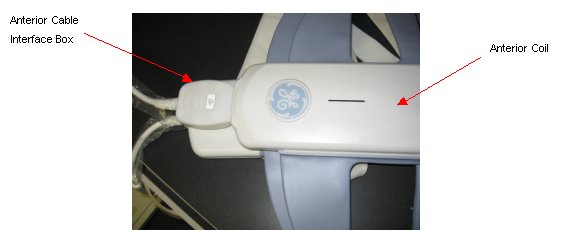
- Remove all the 8 screws form the lower Posterior Coil cover as shown
in the Figure 2; Remove the
cover after removing the screws.
Figure 2. Removal of 8 Screws from Posterior Coil 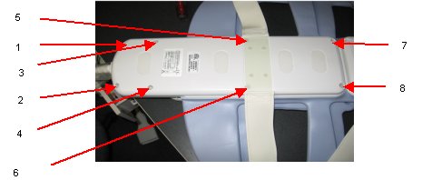
- Insert the new cable to the coil and connect the corresponding RF cables
(J7-J12) to the multiplexer board labeled with J7-J12 SMB connector.
Figure 3. Posterior Coil RF Cable and DC Wire Removal 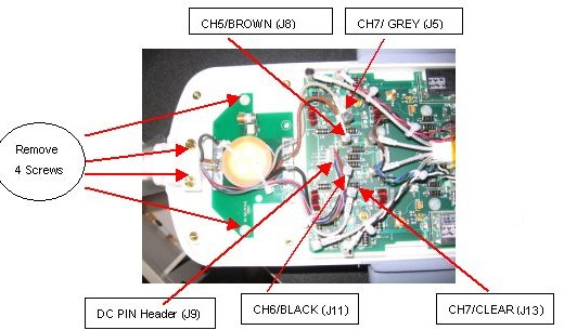
Finalization
No finalization steps.