
- SIGNA MR355 / SIGNA MR360
- Service Manual
- 5856356-3EN Revision 5.0
- Basic Service Documentation. Copyright General Electric Company.
- 00000018WIA30F52F20GYZ
- id_131061243.0
- Aug 29, 2019 1:53:25 AM
HD 8 CH Body Array Coil Setup for SNR Test
Prerequisites
| Required persons | Preliminary requirements | Procedure | Finalization |
|---|---|---|---|
| 1 | 0 minutes | 15 minutes | 0 minutes |
| Item | Quantity | Effectivity | Part number | Manufacturer |
|---|---|---|---|---|
| TL Unified Phantom | 2 | - |
5343347 | - |
| Condition | Reference | Effectivity |
|---|---|---|
|
The following coil configuration names must be installed to run this tool: 8ch Body U service, 8ch Body L service | - | - |
Procedure
- Place the posterior section of the coil on the table. Place
the TL unified phantoms over the posterior section as in Figure 1.
Figure 1. Place the TL unified phantoms 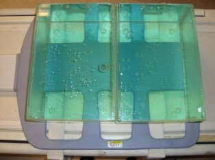
- Place the TL unified phantoms such that the TL unified phantoms
are well centered on S/I direction as shown in Figure 2.
Figure 2. Alignment in S/I 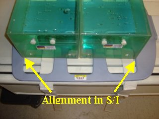
- Place the TL unified phantoms such that the TL unified phantoms
are well centered on R/L direction as shown in arrows in Figure 3.
Figure 3. Alignment in R/L 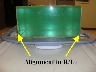
- Place the anterior section on the TL unified phantoms such that
the coil is well centered in both S/I and R/L directions with respect
to the phantom set as shown in the Figure 4 and Figure 5.
Figure 4. Place the anterior section 1 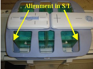
Figure 5. Place the anterior section 2 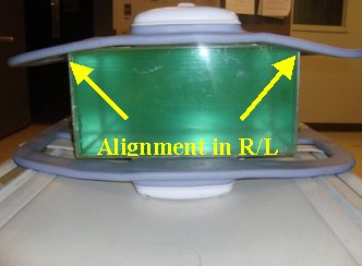
- Landmark the coil at the center cross mark as shown in Figure 6 and advance
to scan.
Figure 6. Landmark 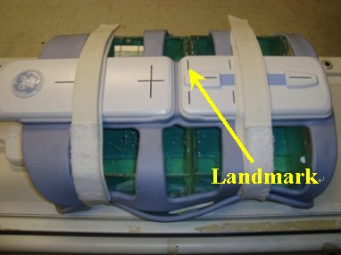
Finalization
No finalization steps.