
- SIGNA MR355 / SIGNA MR360
- Service Manual
- 5856356-3EN Revision 5.0
- Basic Service Documentation. Copyright General Electric Company.
- 00000018WIA30FF5F20GYZ
- id_131057662.0
- Jul 19, 2019 10:59:58 AM
Ground Resistance Checks
Prerequisites
| Required persons | Preliminary requirements | Procedure | Finalization |
|---|---|---|---|
| 2 | Not Applicable | 60 minutes | 5 minutes |
| Item | Quantity | Effectivity | Part number | Manufacturer |
|---|---|---|---|---|
| Digital voltmeter (optional) | 1 | - | - | - |
| Bio-design MG5 meter (Microguard) with Milliohm Adapter | 1 | - |
46-194427P16 | - |
| Dale 600 or 601 (120 VAC) or Dale 600E or 601E (220 VAC) Safety Analyzer | 1 | - |
600/601: 46-285647P1 or 46-328406G1 600E/601E: 46-285647P14 or 46-328406G2 | - |
| Fluke ESA612 Electrical Safety Analyzer | 1 | - |
5453348 | - |
| Personal Lock | 2 | - |
46-194427P320 | - |
| Red Warning LOTO Tag | 2 | - |
46-194427P322 | - |
| Multi-locking Device (If multiple service people) | 1 | - |
46-194427P313 | - |
| Item | Quantity | Effectivity | Part number | Manufacturer |
|---|---|---|---|---|
| Ground Wire | 1 | - |
46-255947G607 or equivalent | - |
| ||||
| Condition | Reference | Effectivity |
|---|---|---|
|
Any required electrical code inspection | - | - |
|
Installation of the facility disconnect device | - | - |
|
EMERGENCY OFF wiring | - | - |
|
PDU primary wiring | - | - |
|
PDU subsystem power cables | - | - |
|
Refer to the System Installation Manual. Power Cable Installation Instructions | - | - |
|
No hard wired signal cables connected to any subsystem cabinets. Fiber Optic cables may be connected and not impact this check. | - | - |
About this task
This document contains a method for measuring ground resistance using different brands of safety analyzers. Only one of the safety analyzers listed in Tools and Test Equipment is required for this procedure.
Review and understand the required conditions before beginning this procedure.
| If you are using | Go to Section |
| Microguard | Ground Resistance Checks Using Microguard |
| Dale 600/600E or 601/601E safety analyzer | Ground Resistance Checks Using Dale (Sites Equipped with Dale 600, 600E, 601, or 601E Safety Analyzer) |
| Fluke ESA612 safety analyzer | Ground Resistance Checks Using Fluke ESA612 |
Ground Resistance Checks Using Microguard
Procedure
Ensure that no power is applied to PDU, see Lockout / Tagout for MDP(Main Disconnect Panel) or Facility PDU.DANGER 
- Plug milliohm adapter module into power outlet of the Microguard.
Figure 1. MICROGUARD CONNECTIONS  Note:
Note:Since the Microguard is being used solely as a voltmeter in this application, any other meter capable of resolving 0.1 millivolts can be substituted in the next step. Meters other than the Microguard are currently in use. Refer to the appropriate tool catalog for further information.
Ground Resistance Checks Using Dale (Sites Equipped with Dale 600, 600E, 601, or 601E Safety Analyzer)
Procedure
Perform PDU LOCKOUT TAGOUT. See Lockout / Tagout for MDP(Main Disconnect Panel) or Facility PDU.DANGER - Connect one clamp-type lead to the EXTERNAL jack on the top of the Dale safety analyzer. Connect the other clamp-type
lead to the CHASSIS jack on the top of the
Dale safety analyzer. See Figure 2.
Figure 2. TOP OF DALE SAFETY ANALYZER 
- On the Dale safety analyzer, set the main selector switch to W - RESISTANCE. See Figure 3.
Figure 3. DALE SAFETY ANALYZER 
- Attach the leads as shown in Figure 4.
(Connect one lead to PDU ground bus bar and the other lead to bare
frame of subsystem cabinet under test.)
Figure 4. DALE 600/600E ANALYZER  Note:
Note:The Dale safety analyzer reads resistance in ohms. For example, a reading of 0.50 equals 500 milliohms.
Ground Resistance Checks Using Fluke ESA612
Procedure
Ensure that no power is applied to the MDP. See the MR Service Safety Manual, PN 5452735.DANGER - Note:Turn on the Fluke meter and select the point to point option on the meter.
At facilities with 110-120 VAC, a fault error may appear when you power the meter on. Press F4 OK to clear the error, and continue.
Figure 5. Fluke ESA612 Safety Analyzer 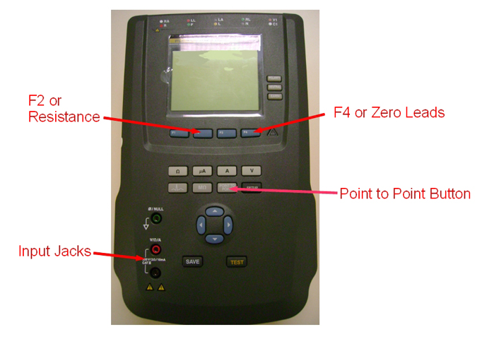
Finalization
Procedure
- Remove LOTO from the MDP and restore power.
- Perform a goodbye scan.