• SIGNA MR355 / SIGNA MR360
  • Service Manual
  • 5856356-3EN Revision 5.0
  • Basic Service Documentation. Copyright General Electric Company.
  • Object ID: 00000018WIA30F65F20GYZ
  • Topic ID: id_13106993 Version: 2.0
  • Date: Jul 19, 2019 11:00:04 AM

Gradient Polarity Checks

Prerequisites

Table 1. Personnel requirements
Required personsPreliminary requirementsProcedureFinalization
10 minutes45 minutes0 minutes
Table 3. Safety

About this task

Reversal of the polarity of a single gradient causes the right/left or top/bottom reversal of the images from two axes, and reversal of the offsets for one axis. Incorrect polarity of all of the gradients causes the images from all planes to be upside down and backward, and causes the system to scan offset images in the opposite direction from those commanded for all axes.

Note:

The values mentioned in this procedure are related to the physical x, y, and z gradient amplifiers, respectively. The values for setting x-, y-, and z-gradient to obtain 1 gauss/cm, respectfully, are in the system configuration file.

Procedure

  1. Place the DQA-III phantom and loader in the head coil. Position it with the fill plugs up, and toward rear of magnet (see Figure 1).
    Figure 1. DQA PHANTOM POSITIONING
  2. Landmark in the sagittal and axial planes (DQA-III coronal plane is not at isocenter).
  3. At front enclosure on scanner, press LANDMARK, then MOVE TO SCAN.
  4. At the Operator Workspace, prepare the system for a “Geometry Verification, Coronal” scan using the scan protocol found in
    Table 4. Coronal Scan Protocol
    SCAN OPTION INPUT
    Patient Register New Pt
    PATIENT INFORMATION
    Patient ID geservice
    Patient Name gradient polarity
    Weight (LB) 111
    Landmark
    Landmark [>]Nasion
    PATIENT PROTOCOLS
    Patient Position [>]Supine
    Patient Entry [>]Head First
    Coil [>]Head Accept
    IMAGING PARAMETERS
    Plane [>]Coronal
    Mode [>]2D
    Pulse Seq [>]Spin Echo Accept
    Imaging Optionsnone (Default)
    PSD Namenone
    Protocolno entry
    SCAN TIMING
    # of Echoes 1 Default
    TE 20
    TR 300
    Bandwidth 15.63
    SCANNING RANGE
    FOV 24
    Sice Thickness 10
    Spacing 1.5
    A/P Start 0
    A/P End 0
    # of Slices 1 Default
    S/I 0 Default
    R/L 0 Default
    Table Delta 0.00 Default
    ACQUISITION TIMMING
    Freq 256
    Phase 256
    NEX 1
    Phase FOV 1:00 Default
    Freq Dir [>]S/I
    Auto Center Freq [>]Peak
    Move To Lowest Window Save Series
    Note:

    The Exam Description name must be exact because it is used by the automated analysis tool (Daily Quality).

  5. Click on Scan (system auto prescans first).
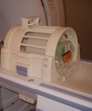
  6. On the scan desktop, click on Autoview. When the image displays, verify that the CS appears in the upper right-hand corner (see Figure 2).
    Figure 2. DQA-III PHANTOM GEOMETRY
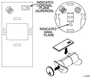
    Note:

    Top/bottom reversal is caused by improper z-gradient polarity (wires crossed between output of Gradient Amplifier and input of Gradient Coil). Left/right reversal is caused by improper y-gradient polarity.

  7. At the Operator Workspace, click on New Series.
  8. At the Operator Workspace, prepare the system for a “Geometry Verification, Axial” scan using the scan protocol shown in Table 5
    Table 5. Axial scan Protocol
    SCAN OPTION INPUT
    Patient Register New Pt
    PATIENT INFORMATION
    Patient ID geservice
    Patient Name gradient polarity
    Weight (LB) 111
    Landmark
    Landmark [>]Nasion
    PATIENT PROTOCOLS
    Patient Position [>]Supine
    Patient Entry [>]Head First
    Coil [>]Head Accept
    IMAGING PARAMETERS
    Plane [>]Axial
    Mode [>]2D
    Pulse Seq [>]Spin Echo Accept
    Imaging Optionsnone (Default)
    PSD Namenone
    Protocolno entry
    SCAN TIMING
    # of Echoes 1 Default
    TE 20
    TR 300
    Bandwidth 15.63
    SCANNING RANGE
    FOV 24
    Sice Thickness 10
    Spacing 1.5
    A/P Start 0
    A/P End 0
    # of Slices 1 Default
    S/I 0 Default
    R/L 0 Default
    Table Delta 0.00 Default
    ACQUISITION TIMMING
    Freq 256
    Phase 256
    NEX 1
    Phase FOV 1:00 Default
    Freq Dir [>]S/I
    Auto Center Freq [>]Peak
    Move To Lowest Window Save Series
    Note:

    The Exam Description name must be exact because it is used by the automated analysis tool (Daily Quality).

  9. Click on Scan (system Auto Prescans first).
  10. When the axial image displays, verify that the A appears in the lower-middle of the image. The image should have the GE logo in the upper right-hand corner (see Figure 2).
    Note:

    Left/right reversal is caused by incorrect polarity of the X gradient. Top/bottom reversal is caused by improper Y gradient polarity.

  11. Click on End and select End Exam to exit.

Finalization

  1. Put away any phantoms and any other tools used for the test.