
- SIGNA MR355 / SIGNA MR360
- Service Manual
- 5856356-3EN Revision 5.0
- Basic Service Documentation. Copyright General Electric Company.
- 00000018WIA3046EF20GYZ
- id_131070051.5
- Apr 23, 2020 7:20:54 PM
FOOT SWITCH AND FOOT PEDAL CABLE
Prerequisites
| Required persons | Preliminary requirements | Procedure | Finalization |
|---|---|---|---|
| 1 | 0 minutes | 30 minutes | 0 minutes |
| Item | Quantity | Effectivity | Part number | Manufacturer |
|---|---|---|---|---|
| Standard Tool (non-ferrous) | 1 | - | - | - |
| ||||||||||||
About this task
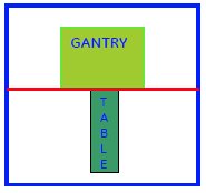
While servicing the table it may be required to disconnect the table from Gantry and required to take out from the magnet room. This instruction provides procedure to take out the table out from the Magnet Room
Procedure
- Remove FRP bottom covers of Fixed Table.
- Remove the Rubber cap and then screws of the FRP bottom cover
on the near the Gantry end of the Table.
Figure 2. FRP Cover1 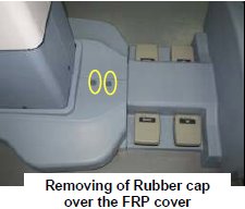
- Similarly remove the cap and screws of the FRP bottom cover
on the rear end of the Table.
Figure 3. FRP Cover2 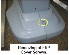
- Remove the right Bottom FRP Cover. Similarly remove the left
Bottom FRP cover on the other side
Figure 4. FRP Cover3 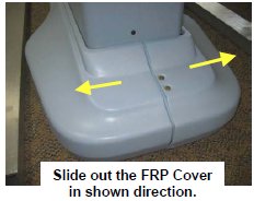
- Now remove the Dock FRP Cover Locking screws and then the Dock
FRP cover carefully.
Figure 5. FRP Cover4 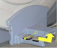
- Remove the Rubber cap and then screws of the FRP bottom cover
on the near the Gantry end of the Table.
- Disconnect the Foot switch Cable from the Control box.
Figure 6. Disconnect the Foot switch Cable 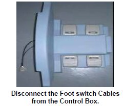
- On the backside of the Dock FRP cover, there are eight screws
holding the four Foot switches.
Figure 7. eight screws 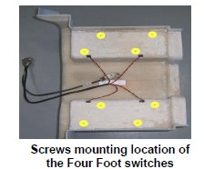
- Remove the screws of the foot switch, which needs to be replaced.
Figure 8. screws of the foot switch 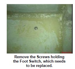
- Push out the foot switch from the Dock FRP cover.
Figure 9. Push out 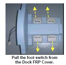
- Open the foot switch with the help of a screwdriver.
Figure 10. Open the foot switch 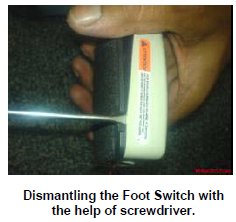
- Rotate the clamp and remove the cable from the clamp.
Figure 11. remove the cable 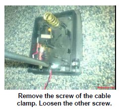
- Disconnect the Cables from the Foot switch.
Figure 12. Disconnect the Cables 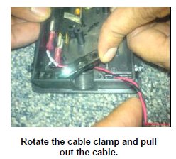
- Now the foot switch is free from the Table. Take the new Foot
switch and Open the foot switch with the help of a screw drive.
Figure 13. Take the new Foot switch 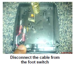
- Connect the foot switch cables to the foot switch.
Figure 14. Connect the foot switch cables 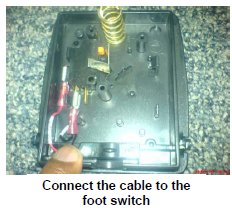
- Remove the right side screw of the cable clamp in the foot switch,
and loosen the other one.
Figure 15. Remove the right side screw 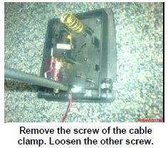
- Rotate the clamp and rout the cable through the clamp.
Figure 16. Rotate the clamp and rout the cable 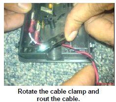
- Tighten the both cable clamp screws.
Figure 17. Tighten the both cable clamp screws 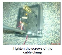
- Assemble the foot switch housing to Foot switch cover with the
help of screwdriver.
Figure 18. Assemble the foot switch 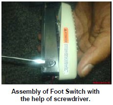
- Place the switch on the FRP Cover, and insert the footswitch
screw from the backside of the Dock FRP cover.
Figure 19. Place the switch on the FRP Cover 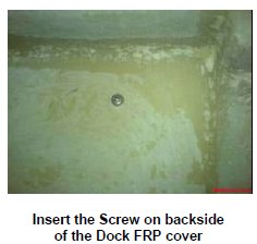
- Pull the cable from the backside of the Dock FRP Cover and rout
cable.
Figure 20. Pull the cable 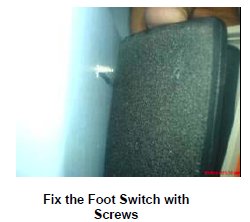
- Now connect the foot switch cable to the control box, placed
in the Gantry.
Figure 21. Connect the foot switch cable 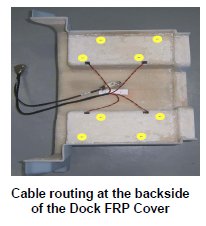
Finalization
Procedure
- Turn the system Power ON. Refer to Lockout / Tagout for System Cabinet PDU Main Breaker.
- Check that Table is up and down normally.