
- SIGNA MR355 / SIGNA MR360
- Service Manual
- 5856356-3EN Revision 5.0
- Basic Service Documentation. Copyright General Electric Company.
- 00000018WIA304DFF20GYZ
- id_131076321.2
- Jul 5, 2019 10:46:04 PM
Enclosure End Covers Removal
Prerequisites
| Required persons | Preliminary requirements | Procedure | Finalization |
|---|---|---|---|
| 4 minumum | - | - | - |
| Item | Quantity | Effectivity | Part number | Manufacturer |
|---|---|---|---|---|
| 12-inch length of 1/2-inch I.D. hose | 1 | - | - | - |
| 2 hose clamps for 1-inch O.D. hose | 1 | - | - | - |
| 4-inch-long piece of copper tubing, 1/2-inch O.D. | 1 | - | - | - |
| Roll of paper toweling | 1 | - | - | - |
| Pair of latex gloves | (optional) | - | - | - |
| Non-magnetic torpedo level or similar | 1 | - | - | - |
| Epoxy-filled Gradient Coil cart (2134810), cradle (2134810-2), and accessory kit (2134810-4). | 1 | - |
2144093 | - |
| Class 1 electric rider lift truck, 4-wheel, rated at 6000 lbs (in case the coil, cart, and cradle must all be lifted together— a necessity in mobiles); with forks a minimum of 56 inches long; with side shifter for easy width adjustment and lateral movement of forks. | 1 | - |
n/a | - |
| Non-magnetic tool kit | 1 | - |
46-320273G1, G2, G3, or G4 | - |
| ||||
| Condition | Reference | Effectivity |
|---|---|---|
|
Verify that the Epoxy-filled Gradient Coil accessory kit contains all the parts listed in Kit Contents. | - | - |
About this task
Perform the following steps at the front of the magnet:
Procedure
- While holding in the Patient Transport Dock Plunger (see Figure 1), move the carriage to the rear of the magnet
by pressing the IN FAST button on the magnet enclosure.
Figure 1. PRESSING PATIENT TRANSPORT DOCK PLUNGER 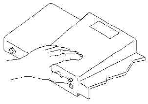
- Remove power to Dock and Long Drive Assemblies by switching off circuit
breaker MR1 A14 CB6 at rear of RF/Pen Cabinet (MR1) on Magnet Enclosure Power
Supply (MEPS) Module (see Figure 2).
Figure 2. LOCKOUT/TAGOUT 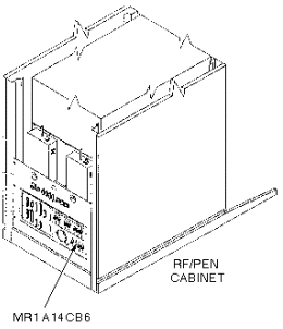
- For enclosure end cover removal, see Figure 3.
Figure 3. REMOVING ENCLOSURE END COVERS 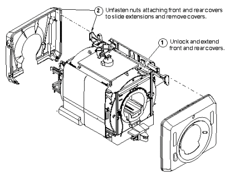
Finalization
No finalization steps.