• SIGNA MR355 / SIGNA MR360
  • Service Manual
  • 5856356-3EN Revision 5.0
  • Basic Service Documentation. Copyright General Electric Company.
  • Object ID: 00000018WIA30DBEF20GYZ
  • Topic ID: id_13106904 Version: 1.1
  • Date: Jul 6, 2019 12:17:31 AM

Cabinet Monitor Functional Check

Prerequisites

Table 1. Personnel requirements
Required personsPreliminary requirementsProcedureFinalization
10 minutes15 minutes0 minutes

Cabinet Monitor Functional Diagnostic

Procedure

  1. Run the Cabinet Monitor Functional Diagnostic.
    1. Open Common Service Desktop.
    2. Select 'Diagnostics / System Function / Peripheral Communications / Cabinet Monitor Functional Diagnostics'.
    3. Select 'Run'.
    Figure 1. Cabinet Monitor Functional Diagnostic
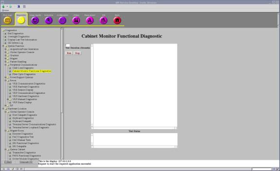
  2. Check the results. Table 2 shows the normal results.
    Table 2. Test Results
    DC Power Supply Data Results Comment
    3.3V DC Power Supply = 3.26 Volts PassThis is an example. Check that 'Pass' is shown.
    5V DC Power Supply = 5.03 Volts PassThis is an example. Check that 'Pass' is shown.
    24V DC Power Supply = 24.22 Volts PassThis is an example. Check that 'Pass' is shown.
    CAN 24V DC Power Supply = 23.93 Volts PassThis is an example. Check that 'Pass' is shown.
    Sensor Data Status
    Leak Sensor2 Leakage NOT DETECT
    Leak Sensor2 Fault NOT DETECT
    Leak Sensor3 Leakage NOT DETECT
    Leak Sensor3 Fault NOT DETECT
    Temp. Sensor Left > 40C NOT DETECT
    Temp. Sensor Left > 45C NOT DETECT
    Temp. Sensor Right > 40C NOT DETECT
    Temp. Sensor Right > 45C NOT DETECT
    Water Tank Level NOT DETECT
    BRM Cooling StatusNORMAL
    Cabinet Cooling StatusNORMAL
    Standby Mode OFF
    Relay Driver Data Status
    Emergency Stop RelayNORMAL
    Pump Shutdown Relay NORMAL

Leak Sensor Test

About this task

There are two Leak sensor routes. This test checks that the each sensor route does not contain broken wire.

  • Leak Sensor 2

  • HDsv Front Leak Sensor Assy 5332131 (Leak sensor 2-A 6613102)

  • HDsv Bottom Leak Sensor Assy 5334211 (Leak sensor 2-B 6613104, Leak Sensor 2-C 6613101, Leak Sensor 2-D 6613104-2)

  • HDsv Water Tray Leak Sensor1 5332992 (Leak sensor 2-E 6613105)

  • Leak Sensor 3

    HDsv Water Tray Leak Sensor2 5332993 (Leak sensor 3 6613105-2)

    This test also checks Sensor Fault LEDs (SF2, SF3) works correctly when disconnecting each sensor cables (Sensor 2, Sensor 3).

    Note:

    Required Condition: Cabinet Monitor Breaker is ON and Sensor Cables (Sensor2, Sensor3) are connected.

Procedure

  1. Check that the each Sensor Fault LEDs (SF2, SF3) is not blinking.
  2. Disconnect sensor 2-A and check that Sensor Fault LED (SF2) blinks. And the PDU is in stop mode.
  3. Turn OFF and turn ON the Cabinet Monitor switch to reset Cabinet Monitor. Reconnect the sensor, press the EMO reset.
    Note:

    It is necessary to turn OFF and turn ON the Cabinet Monitor switch to reset Cabinet Monitor.

    If one disconnected cable is found for Leak Sensor 2, the Sensor Fault LED2 blinks, error message is shown at OC. PDU is in stand by mode.

    If one disconnected cable is found for Leak Sensor 3, the Sensor Fault LED3 blinks, error message is shown at OC.

  4. Repeat step 2 and step 3 for sensor 2-B,2-C,2-D, 2-E and sensor 3.
    Figure 2. Leak Sensor Test
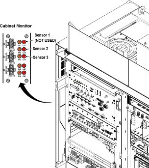
Finalization

Finalization

No finalization steps.