
- SIGNA MR355 / SIGNA MR360
- Service Manual
- 5856356-3EN Revision 5.0
- Basic Service Documentation. Copyright General Electric Company.
- 00000018WIA303DAF20GYZ
- id_131074491.2
- Jul 5, 2019 10:46:04 PM
CRADLE HOME SENSOR CHECK
Prerequisites
| Required persons | Preliminary requirements | Procedure | Finalization |
|---|---|---|---|
| 1 | 0 minutes | 30 minutes | 0 minutes |
| Item | Quantity | Effectivity | Part number | Manufacturer |
|---|---|---|---|---|
| Spanners (1/2,3/4,3/8,7/16,5/16,32) | One for each size | - | - | - |
| Circlip inserter (A-150,A170) | One for each size | - | - | - |
| Hex. Socket (9/16,3/4,3/8) | One for each size | - | - | - |
| Scale (15cms & 30 cms) | One for each size | - | - | - |
| Ball driver (5/32,5/64,3/32,1/8,7/64,9/16) | One for each size | - | - | - |
| Allen key (5/32,5/64,3/32,1/8,7/64,9/16) | One for each size | - | - | - |
| Flat nose plier | - | - | - | - |
| Cutter | - | - | - | - |
| Copper hammer | - | - | - | - |
| Screw driver (8mm, 4mm) | One for each size | - | - | - |
| Knife | - | - | - | - |
| Soft mallet | - | - | - | - |
| Torque wrench (40-120 kg-cm,10 –50 lb-ft) | - | - | - | - |
| Item | Quantity | Effectivity | Part number | Manufacturer |
|---|---|---|---|---|
| Locktite / Primer (242, 569, 680, 415, 770) | One for each size | - | - | - |
| IPA | - | - | - | - |
| White Marker | - | - | - | - |
| Grease Mobil HSC 32 | - | - | - | - |
| Cotton waste White (High grade) | - | - | - | - |
| ||||||||
Procedure
- Remove the Tabletop FRP cover screws and remove tabletop FRP
cover with outer scissor cover.
Figure 1. Remove the panel screws and bent down the Panel 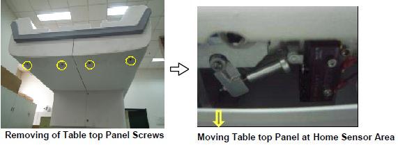
- Actuate the sensor Pin on the Tabletop manually.
Figure 2. Actuate the sensor Pin 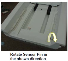
- Ensure that the Push rod engages the Limit switch Dog. If its
not engaging properly adjust the Push rod length by taking in/out
so that it engages properly. Tighten the Push Rod Lock nut after the
adjustment.
Figure 3. Push rod engages the Limit switch Dog 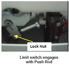
- Ensure that the sensor cables are connected properly with the
Limit switch.
Figure 4. sensor cables 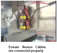
- Fix back the Bottom panels by properly inserting the Side and
Rear bumpers to Panel and FRP.
Figure 5. Fix back the Bottom panels 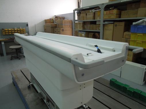
- Recover tabletop FRP cover with outer scissor cover.
Figure 6. Recover tabletop FRP cover with outer scissor cover. 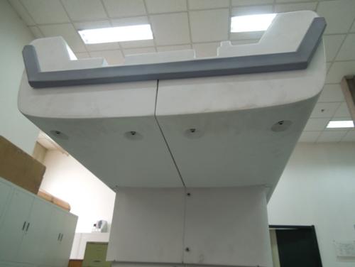
Finalization
No finalization steps.